Categories: Electrician at home, Electric installation work
Number of views: 29399
Comments on the article: 4
How to install a block of electrical switches with a socket
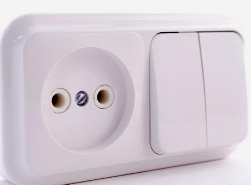 In residential buildings there are multi-key switch designs that are complemented by an electrical outlet. They are usually installed in the corridor on the partition at the entrance of the doors, for example: a bathroom, a bathroom, a kitchen.
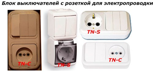
They can be made in the form of vertical or horizontal structures for placement inside installation boxes built into the wall or with a housing for external use.
Such blocks are produced for operation in electrical wiring equipped with the following systems:
-
TN-S;
-
TN-C.
Sockets for connecting to the electrical circuit of an apartment equipped with the TN-S system have additional contacts for connecting working electrical appliances with a protective zero through a PE conductor, and for structures using TN-C circuit, grounding of the housing of household appliances is not applicable.
The figure below shows the various versions of such blocks.
Connection diagram in old buildings
The wiring diagram begins with the apartment panel, in which the circuit breaker that protects our unit is installed, and the working zero bus N. The phase shown by the red line and zero (blue color) are fed from the apartment panel to the junction box with a cable, or more often with a double aluminum wire, popularly called "noodles."
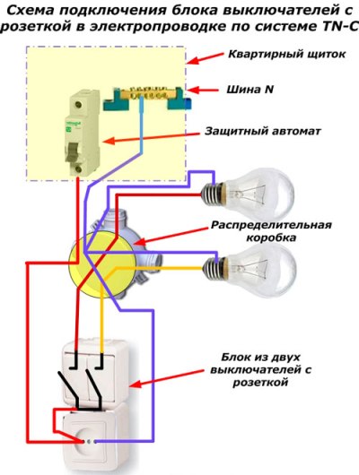
Inside the junction box, all the connections of the wires laid from the lighting devices and the unit in question are made. To do this, it must have connection terminals:
-
suitable phase from the machine;
-
working zero;
-
outgoing phases from the switch to the bulbs.
You can meet the connection of wires by twisting, welding and other methods. Electricians should always have access to them, although many apartment owners hide boxes under false ceilings or wallpaper them for beauty.
Even worse are homeworkers who make wire connections outside junction boxes at various random places. Such disruptions in emergency situations can lead to serious consequences.
The diagram shows that the phase wire through the junction box from the circuit breaker directly approaches the outlet and is removed from its contact to connect to the jumper of the switch, which is shown in the figure with a two-position design. Although it can have three keys for switching additional lighting devices.
From the output contacts of the switches, the phase is directly fed by wire to the remote contacts of the electrons of the lighting devices. For illustration purposes, it is shown in brown and orange colors.
The working zero from the busbar in the apartment panel is fed by a wire (in the figure it is highlighted in blue) to the junction box, where it is connected to other wires going to the socket and cartridges of all bulbs. Any other zero circuit It is considered a violation of the current rules, but, unfortunately, it can often be found in a really laid wiring.
Among the common installation errors, there are cases when the arrangement of the phase and zero is confused: the zero is broken by the switch, and the phase is constantly connected to the electrical receivers. In a similar situation, the switch, of course, works, but the bulbs are constantly under voltage from the mains potential. This is very dangerous for people, especially when replacing blown bulbs.
Connection diagram in new buildings
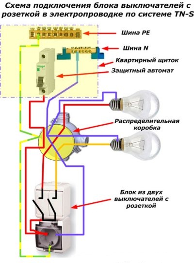
The current standards for electrical safety require the use of a protective zero in the wiring diagram, which connects the housings of household electrical appliances with the ground loop of the electrical installation.For this purpose, a PE conductor and its PE bus are used.
Such buildings are carried out according to the TN-S system, and in old houses, wiring is reconstructed to the TN-C-S scheme. In any case, inside the dashboard, the phase is taken from the circuit breaker, the working zero from the N bus, and the protective one from PE.
Further, the traditional principle of the previously considered connection scheme is used, to which a PE conductor is added. He from his bus through the junction box contact is fed to the grounding contact of the outlet.
The considered schemes are based on the fact that consumers of small capacities are connected to outlets for a short time. In the buildings of the old system, before the load of household appliances rarely exceeded the nominal value of 5 amperes. From the outlets of such blocks, they mainly fed the vacuum cleaner for short-term cleaning of the premises. Its power, coupled with all the working lamps, did not create a current overload of the wiring.
Now such a scheme is a bit outdated: consumer pressures have increased. If it is planned to connect more power to the outlet, then the circuit must be changed. To do this, the cable wires are calculated according to thermal load, additional protective devices are installed: differential switches or - automatic with RCD.
The schematic diagram of the connection of the outlet of our unit will have the following form.
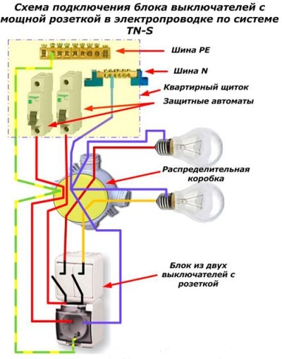
Here in the junction box you will have to provide another socket for connecting the phase of the outlet to the circuit breaker of the apartment panel.
In this scheme, 6 wires are already fed to the unit, which creates difficulties when choosing cables and a junction box. You can lay two three-wire cables for these purposes or change the scheme.
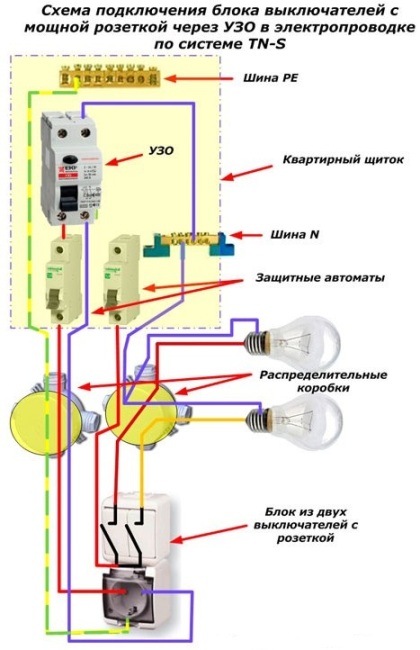
This connection option is the most secure. Here, the RCD protects consumers from possible insulation failures and the potential appearing on the appliance body, while the circuit breaker protects against short-circuit currents.
The electrical characteristics of the socket, machine and RCD must be selected and comply with certain rules. Instead of an RCD and an automatic machine, you can use a differential automatic machine that will perform their protective functions and save space in the apartment panel.
See also:Wiring diagrams in an apartment and a house - the best articles
See also at bgv.electricianexp.com
:
