Categories: How does it work, Auto electrician
Number of views: 150942
Comments on the article: 4
How are battery chargers arranged and working?
Accumulators in electrical engineering are usually called chemical sources of current, which can replenish, restore the consumed energy due to the application of an external electric field.
Devices that supply electricity to the plates of the battery are called chargers: they bring the current source into working condition, charge it. To properly operate the battery, it is necessary to present the principles of their work and the charger.
How the battery works
A chemical recycled current source during operation can:
1. power the connected load, for example, a light bulb, an engine, a mobile phone and other devices, spending its supply of electrical energy;
2. consume the external electricity connected to it, spending it on restoring the reserve of its capacity.
In the first case, the battery is discharged, and in the second it receives a charge. There are many designs of batteries, but their working principles are common. Let us examine this question by the example of nickel-cadmium plates placed in an electrolyte solution.
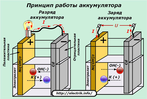
Low battery
Two electrical circuits operate simultaneously:
1. external, applied to the output terminals;
2. internal.
When discharged to a light bulb in an external applied circuit, current flows from wires and a filament formed by the movement of electrons in metals, and anions and cations move through the electrolyte in the inner part.
Graphite-added nickel oxides form the basis of a positively charged plate, and sponge cadmium is used on the negative electrode.
When the battery is discharged, part of the active oxygen of nickel oxides is transferred to the electrolyte and moves to the cadmium plate, where it oxidizes it, reducing the total capacity.
Battery charge
The load from the output terminals for charging is most often removed, although in practice the method is used when the load is connected, such as on the battery of a moving car or on a charged mobile phone that is being talked on.
The battery terminals are supplied with voltage from an external source of higher power. It has the appearance of a constant or smoothed, pulsating form, exceeds the potential difference between the electrodes, is directed unipolarly with them.
This energy causes the current to flow in the internal circuit of the battery in the opposite direction to the discharge, when particles of active oxygen are “squeezed” out of the sponge cadmium and through the electrolyte arrive at their original place. Due to this, the consumed capacity is restored.
During charge and discharge, the chemical composition of the plates changes, and the electrolyte serves as a transmission medium for the passage of anions and cations. The intensity of the electric current passing in the internal circuit affects the rate of restoration of the properties of the plates during charging and the speed of discharge.
The accelerated flow of processes leads to the rapid release of gases, excessive heating, which can deform the design of the plates, disrupt their mechanical condition.
Too small currents during charging will significantly lengthen the recovery time of the consumed capacity. With the frequent use of a delayed charge, the sulfation of the plates increases, and the capacity decreases. Therefore, the load applied to the battery and the power of the charger are always taken into account to create the optimal mode.
The principles of operation of lithium-ion batteries are reviewed here:Chemical current sources
How does the charger work
The current range of batteries is extensive.For each model, optimal technologies are selected that may not be suitable, be harmful to others. Manufacturers of electronic and electrical equipment experimentally study the working conditions of chemical current sources and create their own products under them, which differ in appearance, design, and electrical output characteristics.
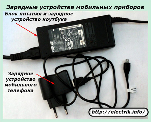
Charging structures for mobile electronic devices
The dimensions of the chargers for mobile products of different capacities are significantly different from each other. They create special working conditions for each model.
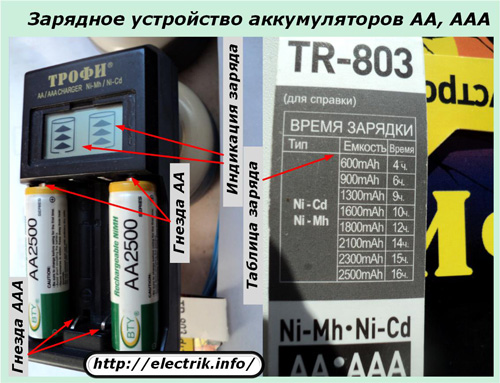
Even for the same type of AA or AAA batteries of different capacities, it is recommended to use your own charging time, depending on the capacity and characteristics of the current source. Its values are indicated in the accompanying technical documentation.
A certain part of the chargers and batteries for mobile phones are equipped with automatic protection that turns off the power at the end of the process. But, control over their work should still be carried out visually.
Charging structures for automotive batteries
Charging technology must be observed with particular precision when operating automotive batteries designed to operate in difficult conditions. For example, in winter, in cold weather, with their help, it is necessary to untwist the cold rotor of the internal combustion engine with thickened grease through an intermediate electric motor - starter.
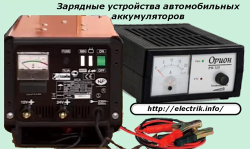
Discharged or improperly prepared batteries usually do not cope with this task.
Empirical methods have revealed the relationship of the charging current for lead acid and alkaline batteries. It is considered to be the optimal value of charge (amperes) of 0.1 value of capacity (ampere hours) for the first type and 0.25 for the second.
For example, a battery has a capacity of 25 amp hours. If it is acidic, then it must be charged with a current of 0.1 ∙ 25 = 2.5 A, and for alkaline - 0.25 ∙ 25 = 6.25 A. To create such conditions, you will need to use different devices or use one universal with a large amount functions.
A modern battery charger for acid lead batteries should support a number of tasks:
-
control and stabilize the charge current;
-
take into account the temperature of the electrolyte and prevent it from heating more than 45 degrees by the termination of power.
The possibility of conducting a control and training cycle for an acid battery of a car using a charger is a necessary function, which includes three stages:
1. A full battery charge to the maximum capacity;
2. ten-hour discharge with a current of 9 ÷ 10% of the nominal capacity (empirical dependence);
3. Recharge a discharged battery.
When carrying out CTC, the change in the density of the electrolyte and the completion time of the second stage are monitored. By its value, they judge the degree of wear of the plates, the duration of the remaining resource.
Chargers for alkaline batteries can be used in less complex designs, because such current sources are not so sensitive to undercharging and overcharging.
The graph of the optimum charge of acid-alkaline batteries for cars shows the dependence of the set of capacitance on the form of current changes in the internal circuit.
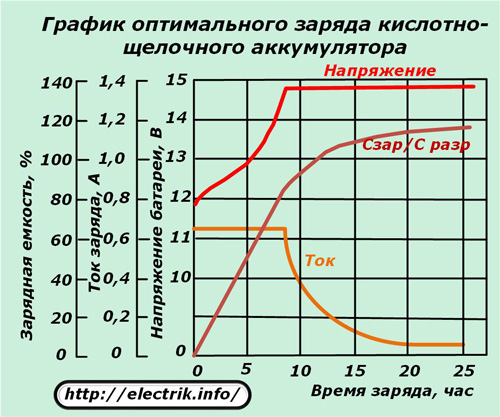
At the beginning of the charging process, it is recommended to maintain the current at the maximum permissible value, and then reduce its value to the minimum for the final completion of the physicochemical reactions that restore the capacity.
Even in this case, it is necessary to control the temperature of the electrolyte and introduce environmental amendments.
The complete completion of the charging cycle of lead acid batteries is controlled by:
-
restoration of voltage on each bank 2.5 ÷ 2.6 volts;
-
achieving maximum electrolyte density, which ceases to change;
-
the formation of violent gas evolution when the electrolyte begins to "boil";
-
achievement of battery capacity, exceeding 15 ÷ 20% of the value given during discharge.
Battery Charger Current Forms
The condition for charging the battery is that voltage should be applied to its plates, which creates a current in the internal circuit of a certain direction. He can:
1. have a constant value;
2. or vary in time according to a certain law.
In the first case, the physicochemical processes of the internal chain proceed unchanged, and in the second, according to the proposed algorithms with cyclic increase and damping, which create oscillatory effects on anions and cations. The latest technology option is used to combat plate sulphation.
Part of the time dependences of the charge current is illustrated by graphs.
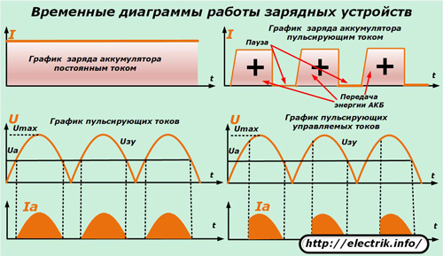
The lower right picture shows a clear difference in the shape of the output current of the charger, which uses thyristor control to limit the opening moment of the half-wave of a sinusoid. Due to this, the load on the electrical circuit is regulated.
Naturally, numerous modern chargers can create other forms of currents that are not shown in this diagram.
Principles of creating circuits for chargers
A single-phase 220 volt network is usually used to power the equipment of chargers. This voltage is converted to safe undervoltage, which is applied to the input terminals of the battery through various electronic and semiconductor components.
There are three schemes for converting industrial sinusoidal voltage in chargers due to:
1. the use of electromechanical voltage transformers operating on the principle of electromagnetic induction;
2. application of electronic transformers;
3. without the use of transformer devices based on voltage dividers.
Technically possible is the inverter voltage conversion, which has become widely used for inverter welding machinesfrequency converters that control motors. But, for charging batteries, this is quite expensive equipment.
Charger circuits with transformer separation
The electromagnetic principle of transferring electrical energy from the primary winding of 220 volts to the secondary completely separates the potentials of the supply circuit from the consumed one, eliminates its contact with the battery and damage in the event of insulation faults. This method is the safest.
The power circuit diagrams of devices with a transformer have many different designs. The picture below shows three principles for creating different currents of the power section from chargers through the use of:
1. diode bridge with a smoothing ripple capacitor;
2. diode bridge without smoothing ripple;
3. A single diode that cuts off the negative half-wave.
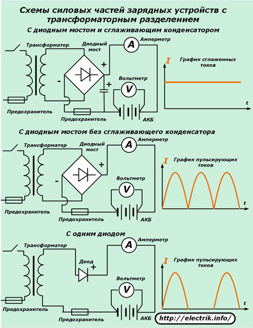
Each of these schemes can be used independently, but usually one of them is the basis, the basis for creating another, more convenient for operation and control by the magnitude of the output current.
The use of sets of power transistors with control chains in the upper part of the picture in the diagram allows to reduce the output voltage at the terminals of the output circuit of the charger, which provides adjustment of the constant currents passed through the connected batteries.
One of the options for this design of the charger with current control is shown in the figure below.
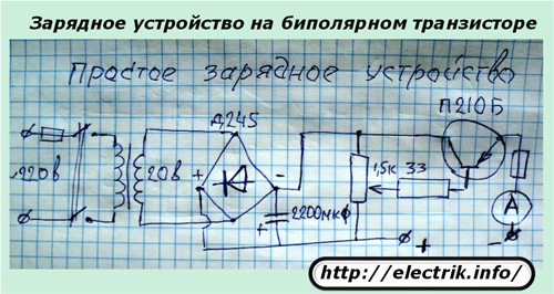
The same connections in the second circuit allow you to adjust the amplitude of the ripple, to limit it at different stages of charging.
The same average circuit works efficiently when replacing two opposite diodes in a diode bridge with thyristors that equally regulate the current strength in each alternating half-cycle. And the elimination of negative half-harmonics is assigned to the remaining power diodes.
Replacing a single diode in the bottom picture with a semiconductor thyristor with a separate electronic circuit for the control electrode allows reducing current pulses due to their later opening, which is also used for various methods of charging batteries.
One of the options for such an implementation of the circuit is shown in the figure below.
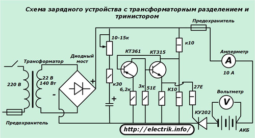
Assembling it with your own hands is not difficult. It can be made independently of the available parts, allows you to charge batteries with currents up to 10 amperes.
The industrial version of the circuit of the Electron-6 transformer charger is based on two KU-202N thyristors. To regulate the opening cycles of the half-harmonics, each control electrode has its own circuit of several transistors.
Among car enthusiasts, devices that allow not only charging batteries, but also using the energy of the 220 volt mains to parallel connect it to starting the car’s engine, are popular. They are called launchers or launchers. They have an even more complex electronic and power circuit.
Electronic Transformer Circuits
Such devices are manufactured by manufacturers to supply halogen lamps with a voltage of 24 or 12 volts. They are relatively cheap. Some enthusiasts are trying to connect them to charge low-power batteries. However, this technology is not widely developed, it has significant disadvantages.
Charger circuits without transformer separation
When several loads are connected in series to a current source, the total input voltage is divided into component sections. Due to this method, dividers work, creating a voltage reduction to a certain value on the working element.
On this principle, numerous chargers with resistive-capacitive resistances for low-power batteries are created. Due to the small dimensions of the component parts, they are built directly into the flashlight.
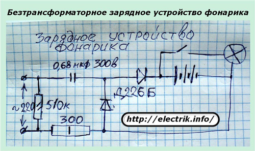
The internal electrical circuit is fully enclosed in a factory insulated case, which excludes human contact with the potential of the network when charging.
Numerous experimenters are trying to implement the same principle for charging car batteries, offering a connection scheme from a household network through a capacitor assembly or an incandescent lamp with a power of 150 watts and power diodetransmitting current pulses of the same polarity.
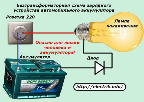
Similar designs can be found on the websites of do-it-yourselfers who praise the simplicity of the circuit, the low cost of parts, and the ability to restore the capacity of a discharged battery.
But, they are silent about the fact that:
-
open wiring 220 represents danger to human life;
-
The filament of a lamp under voltage heats up, changes its resistance according to a law unfavorable for the passage of optimal currents through the battery.
When turned on under load, very large currents pass through a cold thread and the entire series-connected chain. In addition, charging should be completed with small currents, which also does not work. Therefore, a battery that has undergone several series of such cycles quickly loses its capacity and performance.
Our tip: do not use this method!
Chargers are designed to work with certain types of batteries, take into account their characteristics and conditions for the restoration of capacity. When using universal, multifunctional devices, you should choose the charge mode that is optimal for a particular battery.
See also at i.electricianexp.com
:
