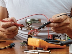
 LED is a rather gentle semiconductor device. If the current through its P-N junction becomes critically larger than the nominal, then overheating will begin and thermal destruction of the crystal will not take long. Therefore, before checking the LED for serviceability, be prepared to be very careful not to accidentally spoil the workpiece.
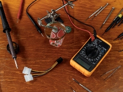
Small round LEDs are designed for an operating voltage in the range of 2 to 4 volts, namely: red, yellow and green - up to 2.2 volts, and white and blue - up to 3.6 volts. The operating rated current of a small round LED usually does not exceed 10 - 20 milliamps, keep this in mind. So, to check the LED, you first need to decide what you will use to check. If there is no multimeter at handthen the first thing you can take a power source with a known voltage in the range from 5 to 12 volts, but do not rush to connect ...
Leakage current in electrical networks, how to check and find leakage current
 Leakage current as a physical phenomenon You have probably heard the expression "leakage current" or "leakage current to earth", but can anyone explain what it is? What causes a leakage current, why is it dangerous, how to eliminate it? We will try to get an answer to these questions.
Firstly, for a leak to occur, a current needs a closed electrical circuit, like any conduction current. And practically any conductive object can become a load here: a person’s body, bathtub, pipe, part of the electrical installation case, etc. And if the leakage current turns out to be excessively high, then there may be a danger to human health. That is why it is necessary to have an idea of this phenomenon. Schematically, the figure shows the path that the leakage current has laid for itself through the human body. Why did the current go through the body in this example? Because the resistance between the housing and the live parts of the installation ...
Inductor to protect against common mode noise generated by a switching power supply
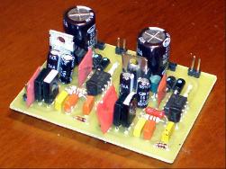
 Common-mode choke is the most important component of the input filter of any switching power supply. The fact is that during the operation of a pulse converter of any topology, when switching field-effect transistors, common-mode interference occurs, which propagate in the conductors and along the tracks of the printed circuit boards.
These interferences are harmful high-frequency impulse currents that flow simultaneously along the plus and minus wires, and in the same direction. If these interference finally gets into the AC power network, then they can not only lower the quality of functioning of the devices included in the network in the neighborhood, but even disable them, especially the signal circuits of digital units. For this reason, today all household appliances, which in principle can become sources of common-mode interference, are equipped with common-mode chokes ...
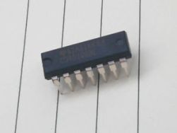
Chip 4046 (K564GG1) for devices with resonance retention - the principle of operation
 When creating a power electronic device with resonance retention in the LC circuit, a resonant controller circuit is designed to synchronize the received oscillations with control pulses coming from the driver. The task of this controller is to keep resonant oscillations in the LC circuit by exciting it in time with its own oscillations.
The controller needs to receive a signal from the loop from the loop containing data on the current frequency and phase of free oscillations in it, after which, relying on these data, support the driver stage in synchronization with these frequencies and phases, then the resonance in the loop will automatically save.To build such a controller, the CD4046 chip or its domestic counterpart K564GG1 is suitable. Let's look at the device of this microcircuit, the purpose of its conclusions and the connection diagram of the mounted componentsto understand what you are dealing with if necessary ...
Simple RC circuit for rectangular pulse delay
 During the development of a pulse converter controller, for example, to construct a circuit with resonance retention, it may be necessary to delay the edges of the pulses and the decay of the pulse sequence when a rectangular signal is applied from one block of the circuit to another.
Sometimes a simple circuit consisting of two logical inverters and an RC circuit is suitable for solving this problem. For this purpose, it is convenient to use a microcircuit, which is a set of inverters with sufficiently defined thresholds. An example of such a microcircuit is 74N0404, there are 6 “NOT” logic elements in it, and it turns out that on one such microcircuit it is theoretically possible to construct 3 delay circuits according to the scheme below. In practice, when the decay of the rectangular pulse arrives at the input of the first inverter, the leading edge comes to the RC circuit from its output, and the capacitor starts charging ...
Bootstrap capacitor in a half-bridge control circuit
 Integrated circuits - half-bridge drivers, such as, for example, IR2153 or IR2110, involve the inclusion in the general circuit of a so-called bootstrap (detached) capacitor for independent power supply to the upper key control circuit. While the bottom key is open and conducting current, the bootstrap capacitor is connected through this open bottom key to the negative power bus, and at this time it can receive charge through the bootstrap diode directly from the driver's power source.
When the lower key is closed, the bootstrap diode stops supplying charge to the bootstrap capacitor, since the capacitor is disconnected from the negative bus at the same moment, and now can function as a floating power source for the gate control circuit of the upper half-bridge key. Such a solution is quite justified, because the power often required for key management is relatively small, and the energy spent can simply be periodically replenished ...
Schmitt trigger - general view
 During the design of the pulse circuit, the developer may need a threshold device that could form a pure rectangular signal with certain values of high and low voltage levels from the input signal of a non-rectangular shape (for example, sawtooth or sinusoidal). The Schmitt trigger, a circuit with a pair of stable output states, which under the influence of the input signal, replace each other in a jump, is well suited for this role, that is, the output is a rectangular signal.
A characteristic feature of the Schmitt trigger is the presence of a certain range between the voltage levels for the input signal, when the output voltage of the input signal is switched over at the output of this trigger from a low level to a high one and vice versa. This property of a Schmitt trigger is called hysteresis, and the portion of the characteristic between the threshold input values ...
Discrete Component Field Effect Transistor Driver
 It’s one thing when there is a ready-made driver in the form of a specialized microcircuit like UCC37322 for high-speed control of a powerful field-effect transistor with a heavy gate, and it’s quite another when there is no such driver, and the power switch control scheme must be implemented here and now.
In such cases, it is often necessary to resort to the help of discrete electronic components that are available, and already from them to assemble the shutter driver.The case, it would seem, is not tricky, however, in order to obtain adequate time parameters for switching the field-effect transistor, everything must be done efficiently and work correctly. A very worthwhile, concise and high-quality idea with the goal of solving a similar problem was proposed back in 2009 by Sergey BSVi in his blog. The circuit was successfully tested by the author in the half-bridge at frequencies up to 300 kHz. In particular, at a frequency of 200 kHz, with a load capacitanceat 10 nF ...