Categories: Microcontroller circuits
Number of views: 24878
Comments on the article: 0
What are the displays for Arduino and how to connect them
Microcontrollers allow you to make any automation and monitoring system. But for the interaction of technology and man, we need both input devices - various buttons, levers, potentiometers, and output devices - light indicators (bulbs), various sound signaling devices (tweeters), and finally displays. In this article, we will look at character displays for Arduino, how to connect them and make them work.
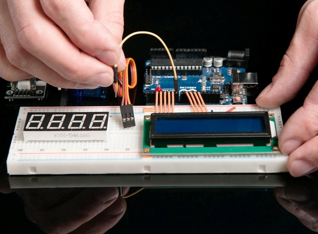
Types of displays
Displays can be divided into:
-
Segment (such as on a digital watch);
-
Alphanumeric;
-
Graphic.
Segmented are used to indicate simple quantities, for example: temperature, time, number of revolutions. Such are used in calculators and on budget household appliances to this day. Information is displayed by highlighting certain characters.
They can be both liquid crystal and LED. Alphanumeric displays can be found on old household appliances, toys, industrial equipment and more. They are also called sign-synthesizing, textual, symbolic. Consist of a set of large pixels. Can be performed on LCD, TFT and OLED technology.
Graphic displays can even include a monitor or a smartphone screen, I think no special explanations are required. The article will focus specifically on the collaboration of sign-synthesizing or symbolic displays and Arduino.
Sign-Synthesizing Displays
Displays of this kind can simultaneously display a certain number of characters, limited by geometric dimensions. They are marked according to this pattern:
-
1602;
-
2002.
Where the first two digits is the number of characters in the line, and the second pair is the number of lines. Thus, a display called 1602 can display 2 lines of 16 characters at a time.
Displays are distinguished by the type of data input:
-
With parallel data entry;
-
With data input via I2C protocol.
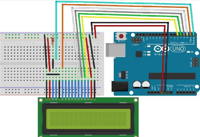
Parallel data input involves the transfer of 8 or 4-bit words on 10 or 6 pins, respectively (Fig. Below - connection diagram for controlling 4 bits). In addition to data, power is supplied to the display. Consider this when designing, otherwise you may not have enough pins Arduino boards.
Transferring data to the display using I2C will take 4 pins of your Arduino, 2 of which are power, and 2 is data. But consider this question in more detail below.
Among domestic manufacturers can distinguish the company MELT. Among the products, which have a number of different displays. For example, below is a display labeled 20S4, similar to the previous one, it tells us that it displays 4 lines of 20 characters.
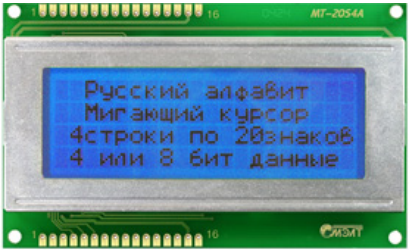
It is built on the controller KB1013VG6, from JSC ANGSTREM, which is similar to HD44780 from HITACHI and KS0066 from SAMSUNG. On which the vast majority of Chinese displays are built. By the way, he, like displays on the above chips, supports the standard Arduino IDE parallel control library, but more on that later.
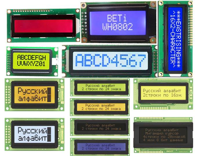
Sign-synthesizing displays come with and without backlighting, and may also differ in the color of the displayed characters. Backlight brightness and image contrast are usually adjustable. Below is an example of a scheme from a datasheet, to the MELT mentioned above.
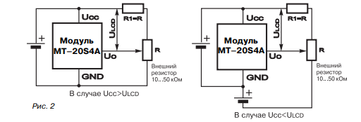
Variable resistor R and serves to adjust the brightness.
Connection
We will consider the connection on a display of type 1602. First of all, pay attention to the signature of the conclusions. There are two options, numbering. In the two figures below, everything is fine - from 1 to 16 of the output.
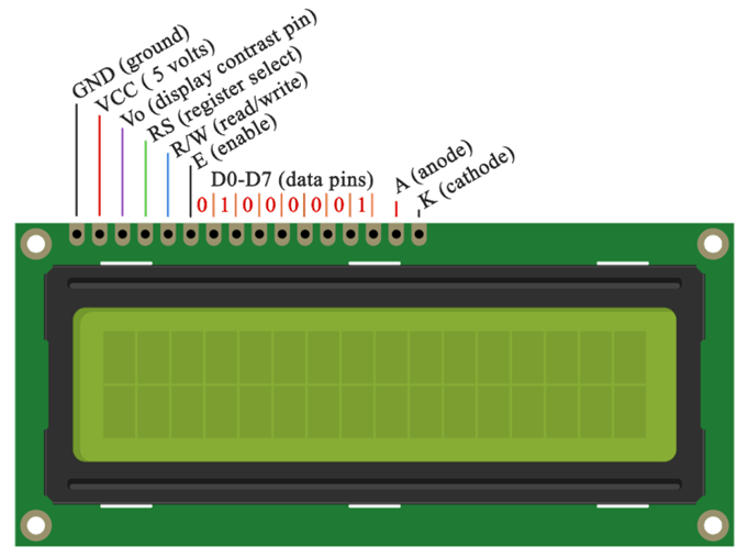
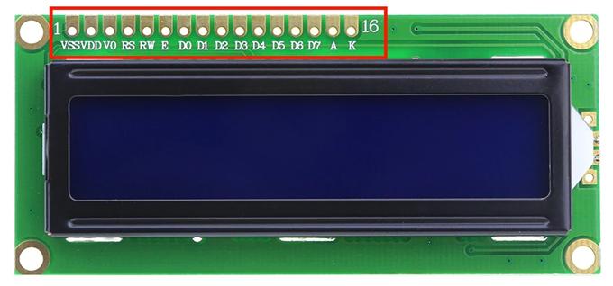
Note that VSS is understood as land. Otherwise, the pin assignments are identical. But often you can find non-standard numbering:
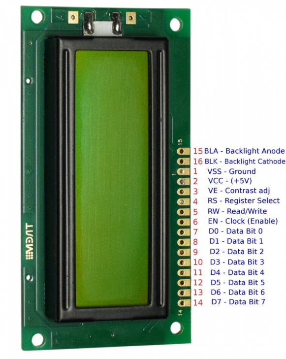
What do you see? Contacts are signed only 1, 14 and 15. Moreover, in the wrong sequence. Otherwise, the 15th and 16th contacts also remained the anode and cathode of the backlight, and 1 and 2 are the common contact and plus power.Be careful and pay attention to this fact when connecting!
Let's analyze in more detail.
-
1 - (Vss) ground or “-” power.
-
2 - (Vcc) "+" power. Most often it is 5 volts.
-
3 - adjusts the contrast of characters. It is carried out through a potentiometer installed between the "+" power and this contact. The higher the voltage, the lower the brightness and power consumption.
-
4 - (RS) Address signal. By the presence of a signal from the arduino at this input, the display controller understands whether the command signal (moving the cursor, for example) or the character code to display on the data line.
-
5 - (E) permissions to access data. When there is a logical “1”, the display executes a command or displays a symbol.
-
6-14 - through these pins parallel data entry is provided.
-
15 - (BLA) backlight anode. So that it lights up at full brightness - + 5V is supplied here.
-
16 - (BLC) backlight cathode. Connect to the ground.
One of the examples of connecting to Arduino in 4-bit mode was discussed above. Now take a look at the wiring diagram in 8 bit control mode. By the way, you might notice a variable resistor. It is needed to adjust the brightness of the backlight, as mentioned earlier.
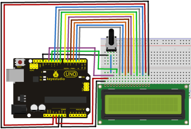
This way you have half of the entrances occupied Arduino UNO Boards. Of course, if you use MEGA, this will not be a significant problem, but still it is not rational, especially if you are going to connect a group of sensors and control keys.
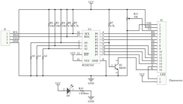
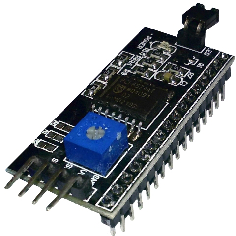
To free up the inputs, use the I2C converter for the LCD screen (that's what it is called, and you can find it in stores under that name).
Attention:
If you will buy this module separately from the display, do not forget about the location and numbering of the terminals, which we examined earlier.
The comb shown at the bottom is simply soldered to the display, and the four pins on the end of the board connect to the Arduino pins, there is also a third group of two pins (pictured in the back) that turns on the backlight, the models come with a jumper installed.
The scheme of such a module is as follows:
And so it looks soldered directly to the display pins. Most models are sold already soldered.
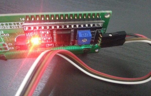
However, to use it, you will need to find the LiquidCrystal_I2C library on the network, it is not in the standard set of the current Arduino IDE at the time of writing.
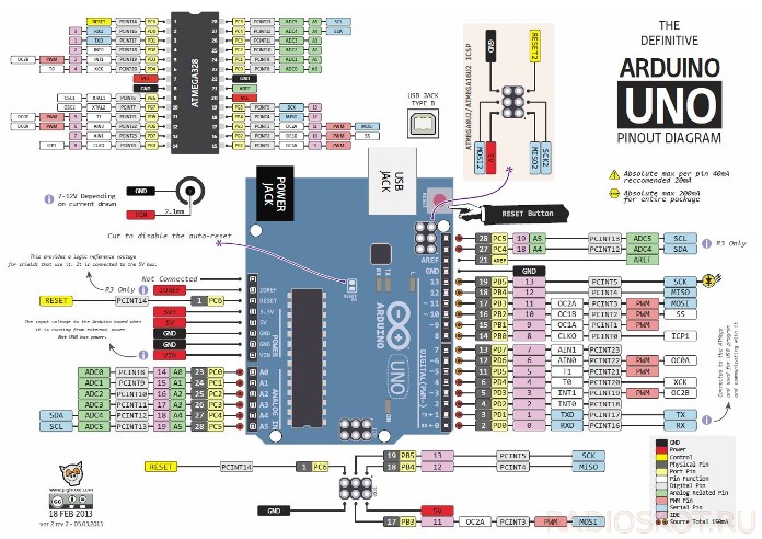
Recall the pinout of the Arduino UNO boards, according to the pin numbering, it basically coincides with Nano and some others (click on the picture to enlarge).
To work on I2C, you need to generate 2 information signals - SDA and SCL, pay attention to the lower right corner of the figure. These Arduino pins are combined with A4 and A5 analog inputs.
Important:
You cannot reassign them to other conclusions.
Then the wiring diagram will look like:
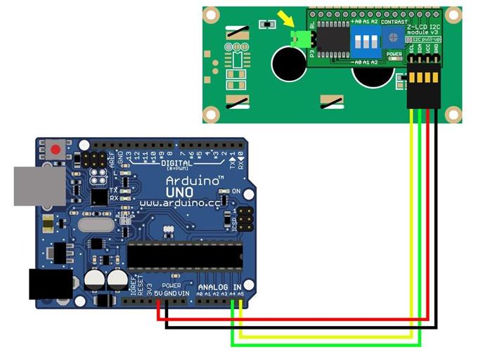
Agree, there are much fewer wires! From arduino to the display are only 4 wires. A signal pin used only two!
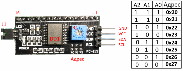
But just connecting you won’t succeed, you need to know the device address, for this there is another group of contacts where the address is set using jumpers. This is indicated in the initialization command of the corresponding library, more on that below.
Program
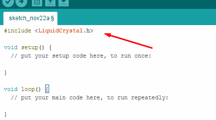
Naturally, we need some kind of sketch that can show the image on a character display. If you want to work directly with the display, you will have to study datasheets and symbol tables for each specific product. But Arduino was created for simple and quick prototyping of electronic devices. Therefore, we will go the other way and take advantage of the benefits of civilization. We have already mentioned that the standard set of libraries in the Arduino IDE has a ready-made solution for working with LCD displays. You can find it here:
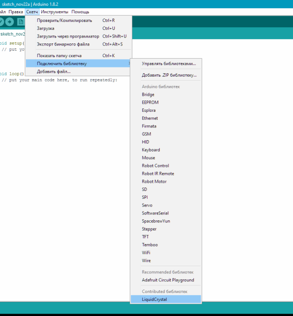
By the way, after clicking the line with the announcement about connecting the library appears automatically.
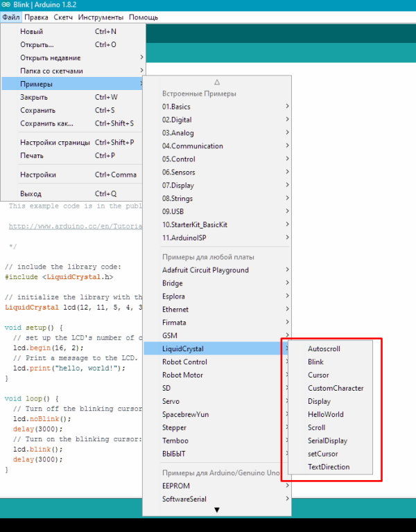
Also in the Arduino IDE there are several examples for working with the display. They reflect basic operations and functions.
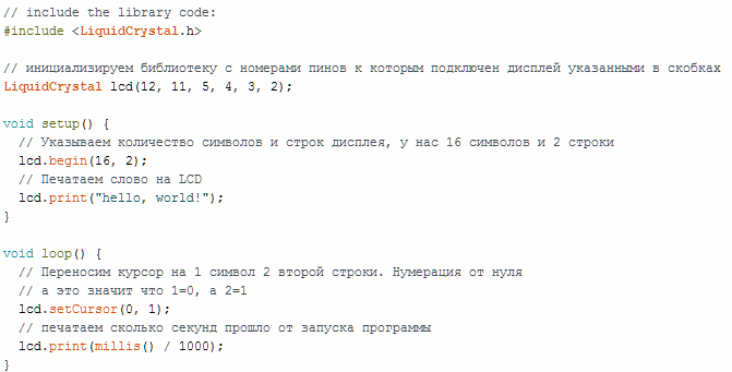
Consider the simplest "Hello Word". The example completely coincides with what is in the standard IDE set, I just translated the text of the comments into Russian.Please note this is an example of working in 4-bit mode.
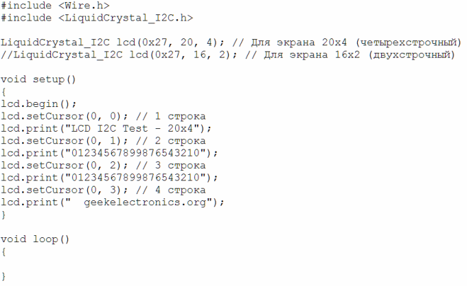
Working with I2C is almost the same:
IMPORTANT:
Please note that in this code example, the first command indicates several display sizes, the number of lines and characters, but also its I2C address. Namely - 0x27, which corresponds to missing jumpers. In general, this is necessary in order to connect several displays (8 pieces) to two signal wires.
A selection of video tutorials on the topic
So that it would not be difficult for you to master the skill of working with the display, we have made a selection of video lessons on this topic.
Conclusion
It turns out that making the Arduino board friends and the display is not at all difficult. You have the opportunity of both parallel data transfer and serial via the I2C bus, what to choose - you decide, both in terms of convenience and the speed requirements of the system as a whole. Write in the comments what questions you need to consider in more detail and what exactly would you like to see on the topic of microcontrollers!
For more information about Arduino and the features of its use in various schemes, see the e-book - Arduino for dummies. Illustrated practical guide.
Most recently, a new course by Maxim Selivanov "Programming Nextion Displays" has been released. This is the "arduino" in the world of touch screen displays. But, information on it is very small.
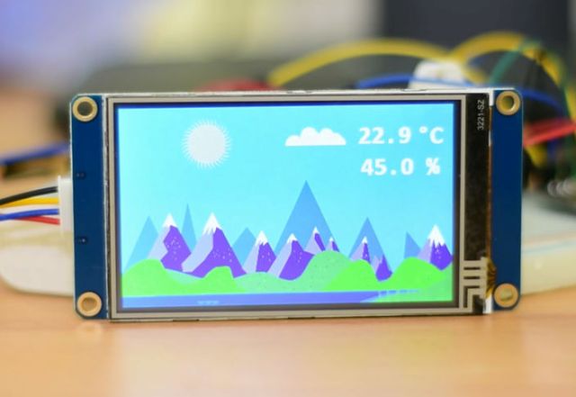
What are Nextion Displays? In short, these displays are programmable displays with a touchscreen and UART to create a variety of interfaces on the screen. For programming, a very convenient and simple development environment is used, which allows you to create even very complex interfaces for various electronics in just a couple of evenings! And all the commands are transmitted via the UART interface to the microcontroller or computer.
There is everything to start working with Nextion displays at a new level: NEXTION
See also at i.electricianexp.com
:

