Categories: Microcontroller circuits
Number of views: 32596
Comments on the article: 0
How to check the microcontroller for serviceability
In repairing equipment and assembling circuits, you always need to be sure that all elements are in good working order, otherwise you will waste your time. Microcontrollers can also burn out, but how to check it if there are no external signs: cracks in the case, charred areas, burning smell, and so on? To do this, you need:
-
Power supply with stabilized voltage;
-
Multimeter;
-
Oscilloscope.
Attention:
A full check of all the nodes of the microcontroller is difficult - the best way to replace it with a known good one, or with the existing one, upgrade another program code and check its execution. In this case, the program should include both checking all the pins (for example, turning on and off the LEDs after a specified period of time), as well as interrupt circuits and other things.
Theory
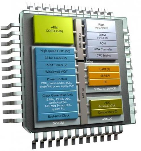
Microcontroller Is a complex device in it multifunctional nodes:
-
power circuits;
-
Registers
-
inputs and outputs;
-
ALU;
-
RAM
-
ROM
-
ADC;
-
interfaces and more.

Therefore, when diagnosing a microcontroller, problems arise:
The operation of obvious nodes does not guarantee the operation of the remaining components.
Before proceeding with the diagnosis of any integrated circuit, you need to familiarize yourself with the technical documentation in order to find it, write in a search engine a phrase like: "name of the datasheet element", as an option - "atmega328 datasheet".
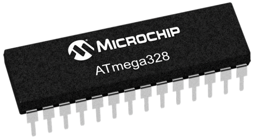
On the very first sheets you will see basic information about the element, for example, consider individual moments from the datasheet to the common 328th atmega, for example, we have it in the dip28 package, we need to find the pinout of the microcontrollers in different packages, consider the dip28 that interests us.
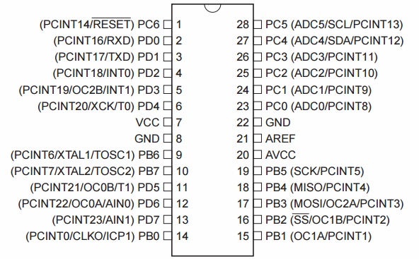
The first thing we will pay attention to is that pins 7 and 8 are responsible for plus power and a common wire. Now we need to know the characteristics of the power circuits and the consumption of the microcontroller. The supply voltage is from 1.8 to 5.5 V, the current consumed in the active mode is 0.2 mA, in the low-power mode it is 0.75 μA, and a 32 kHz real-time clock is included. Temperature range from -40 to 105 degrees Celsius.
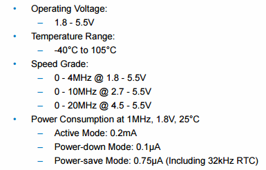
This information is enough for us to conduct a basic diagnosis.
Main reasons
Microcontrollers fail, both for uncontrolled circumstances and because of improper handling:
1. Overheating during operation.
2. Overheating during soldering.
3. Overload of conclusions.
4. Reverse power supply.
5. Static electricity.
6. Power surges.
7. Mechanical damage.
8. Exposure to moisture.
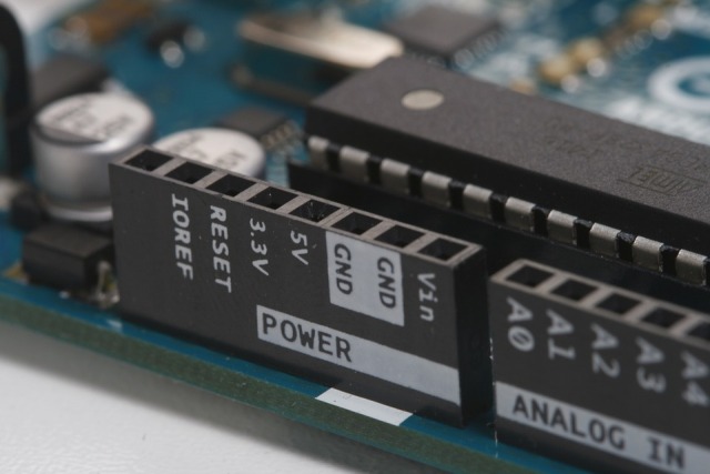
Consider in detail each of them:
1. Overheating can occur if you operate the device in a hot place, or if you have placed your design in a too small case. The microcontroller’s temperature can also be increased by too tight installation, improper PCB layout, when there are heating elements next to it - resistors, power transistors, linear power regulators. The maximum allowable temperatures of common microcontrollers are in the range of 80-150 degrees Celsius.
2. If you solder with a too powerful soldering iron or hold the sting on its legs for a long time, you can overheat microns. Heat through the leads will reach the crystal and destroy it or its connection with the pins.
3. Overloading of the terminals occurs due to incorrect circuitry solutions and short circuits to the ground.
4. Polarity reversal, ie the supply of minus power to Vcc, and plus to GND, may be due to improper installation of the IC on the circuit board, or incorrect connection to the programmer.
5. Static electricity can damage the chip, both during installation, if you do not use antistatic attributes and grounding, or during operation.
6. If a malfunction occurs, the stabilizer breaks out, or for some reason, the microcontroller has a voltage higher than the permissible voltage - it is unlikely to remain intact.It depends on the duration of the emergency.
7. Also, do not be too zealous when mounting the part or disassembling the device so as not to damage the legs and the case of the element.
8. Moisture becomes the cause of oxides, leads to loss of contacts, short circuit. And we are talking not only about the direct hit of liquid on the board, but also about long-term operation in conditions with high humidity (near ponds and basements).
Checking the microcontroller without tools
Start with an external examination: the case must be intact, the soldering of the terminals must be impeccable, without microcracks and oxides. This can even be done with ordinary magnifying glass.
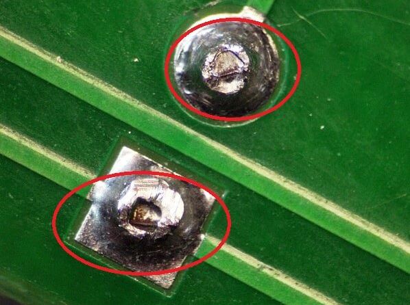
If the device does not work at all, check the temperature of the microcontroller; if it is heavily loaded, it can heat up, but not burn, i.e. the temperature of the case must be such that the finger tolerates with long holding.You won’t do anything without a tool.
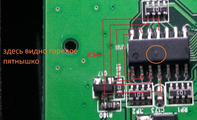
Multimeter check
Check for voltage coming to Vcc and Gnd. If the voltage is normal, you need to measure the current, for this it is convenient to cut the track leading to the Vcc power output, then you can localize the measurements to a specific microcircuit, without the influence of elements connected in parallel.
Do not forget to strip the board cover to the copper layer in the place where you will touch the probe. If you cut it carefully, you can restore the track with a drop of solder, or a piece of copper, for example from the transformer winding.
Alternatively, you can power the microcontroller from an external 5V power supply (or other suitable voltage), and measure the consumption, but you still need to cut the track to exclude the influence of other elements.
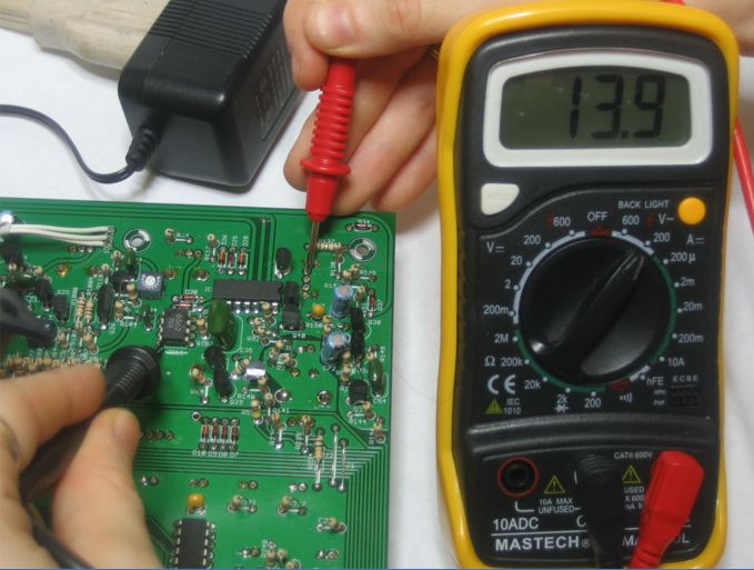
For all measurements, we need enough information from the datasheet. It will not be superfluous to see what voltage the power regulator for the microcontroller is designed for. The fact is that different microcontroller circuits are powered by different voltages, it can be 3.3V, 5V and others. Voltage may be present but not match the rating.
If there is no voltage, check if there is a short circuit in the power circuit, and on the other legs. To quickly do this, turn off the power to the board, turn on the multimeter in dialing mode, put one probe on the board's common wire (ground).
Usually it passes along the perimeter of the board, and at the attachment points with the case there are tinned platforms or on the connector housings. And the second, draw on all the conclusions of the chip. If he buys somewhere - check what kind of pin it is, the dialing should work on the GND pin (8th pin on atmega328).
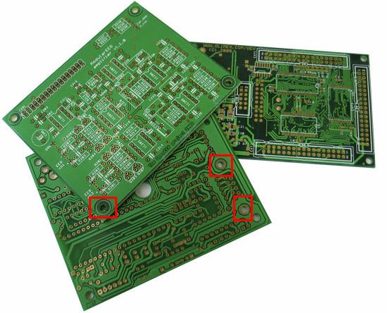
If it doesn’t work, the circuit between the microcontroller and the common wire may be broken. If it worked on other legs - see the diagram for low resistance between the pin and minus. If not, you need to remove the microcontroller and ring again. We check the same thing, but now between the plus power (with the 7th pin) and the terminals of the microcontroller. If desired, all legs are phoned together and the connection diagram is checked.
Oscilloscope Test
Oscilloscope - the eyes of an electronics engineer. With it, you can check for lasing on the resonator. It connects between the terminals XTAL1,2 (legs 9 and 10).
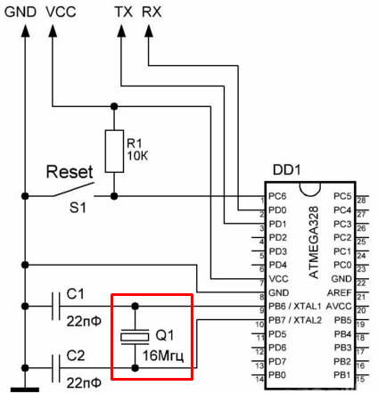
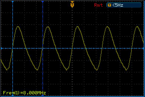
But the oscilloscope probe has a capacitance, usually 100 pF, if you set the divider to 10, the probe capacitance drops to 20 pF. This makes a change to the signal. But to test the performance it is not so essential, we need to see if there are any fluctuations at all. The signal should have a shape like this, and the frequency corresponding to a specific instance.
If the circuit uses external memory, then you can check very easily. There should be bursts of rectangular pulses on the data line.
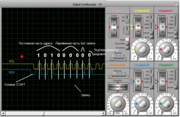
This means that the microcontroller correctly executes the code and exchanges information with memory.
We use a programmer
If you remove the microcontroller and connect it to the programmer, you can check its reaction.To do this, in the program on the PC, click the Read button, after which you will see the ID of the programmer, on AVR you can try to read fuses. If there is no read protection, you can read the firmware dump, download another program, check the operation on the code you know. This is an effective and easy way to diagnose microcontroller malfunctions.
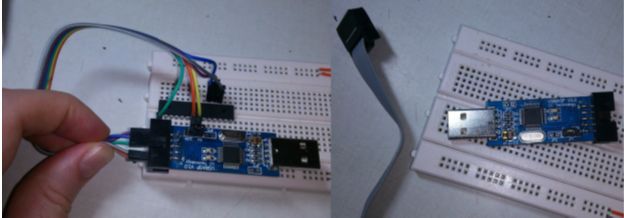
The programmer can be either specialized, such as USBASP for the ATS family:
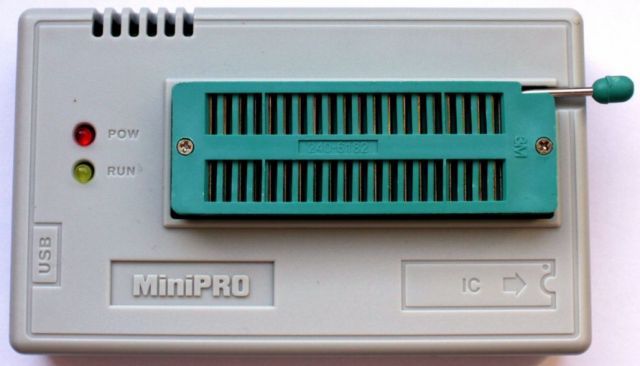
And universal, such as Miniprog.
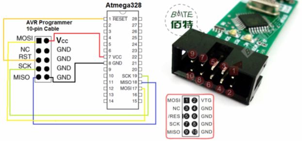
Connection diagram USBASP to atmega 328:
Conclusion
As such, checking the microcontroller is no different from checking any other microcircuit, unless you have the opportunity to use the programmer and read the information from the microcontroller. So you are convinced of its possibility of interconnection with the PC. However, malfunctions do occur that cannot be detected in this way.
In general, the control device rarely fails, more often the problem is the binding, so you should not immediately go to the microcontroller with all the tools, check the entire circuit so as not to get problems with subsequent firmware.
See also at bgv.electricianexp.com
:
