Single-phase induction motor control device
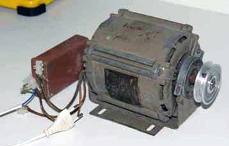 The proposed device can be used to control single-phase asynchronous motors, in particular, for starting and braking an asynchronous motor (HELL) with a short-circuited rotor of low power, having a starting winding or starting capacitor, disconnected before the end of the start. It is possible to use the device to start more powerful asynchronous motors, as well as to start three-phase motors operating in single-phase mode.
In the known device, repeated normal start-up is possible only after the thermistor has cooled and the braking mode of the robot is not ensured. The proposed device has wider functionality.
The device contains a two-pole switch SA1 for two positions, with the help of which the working winding P of the induction motor and the winding of the electromagnetic relay K1 are connected through the rectifier diode VD1, a timing RC circuit consisting of a parallel connected resistor R1 and an electrolytic capacitor C1. The closing contact K1.1 relay K1 is used to connect the starting winding II HELL to the mains through the phase-shifting element C2 and switch SA1.
In the starting position, the electromagnetic relay coil ...
A multimeter for dummies: the basic principles of measuring with a multimeter
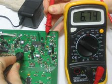 The article is dedicated to all beginners and just those for whom the principles of measuring the electrical characteristics of various components are still a mystery ...
On sale, you can find two main types of multimeters: analog and digital.
In an analog multimeter, the measurement results are observed by the movement of the arrow (like on a clock) on a measuring scale on which the values are written: voltage, current, resistance. On many (especially Asian manufacturers) multimeters, the scale is not very conveniently implemented and for someone who first took such a device in his hand, measurement can cause some problems. The popularity of analog multimeters is explained by their availability and price ($ 2-3), and the main drawback is some error in the measurement results. For more accurate tuning in analog multimeters, there is a special tuning resistor, manipulating which you can achieve a little more accuracy. However, in cases where more accurate measurements are desired, the use of a digital multimeter is best.
The main difference from analog is that the measurement results are displayed on a special screen (in older models using LEDs, in new ones on a liquid crystal display). In addition, digital multimeters have higher accuracy and are easy to use, since you do not have to understand all the intricacies of graduation of the measuring scale, as in arrow versions. A little more about what is responsible for ..
How to make a do-it-yourself indicator of connecting electrical appliances to a 220V network
 Indication device allows you to monitor when leaving home: are electrical appliances disconnected from the network? If any load with a power> 8 W remains on, then both LEDs HL1 and HL2 light up (see figure). The brightness of the glow is small at a load of 8 watts (a dot in the LED is on), therefore, in bright light, to see the glow, you need to cover with your palm the penetration of bright light on the LED. LED (s) are installed at the front door. Conductors to them (0.2 mm) are laid under the wallpaper (due to the small current passing through them). LED HL2 can be excluded from the circuit, and if it remains, then HL1 can be installed on the inside of the door, and HL2 - on the outside.
As a T1 transformer, ready-made ones are used, which have a winding with a large number of turns (2000-3000, or maybe less) and it is possible to wind 8 to 10 turns of a mounting wire of sufficient cross-section. In each particular transformer, the number of turns is selected experimentally. These 8 - 10 turns will be the primary winding of the transformer, and the secondary - those that are in the finished transformer ...
What you need to know when installing an RCD and grounding device in an apartment or private house
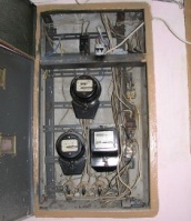 It is not necessary to use RCDs or electronically controlled difavtomats, for example, IEK AD 12, IEK AD 14 diflavtomats, when the phase or neutral conductor breaks, the power of the electronic control circuit is de-energized and the differential protection stops working. There is a diffrel with an electronic control circuit in which, in the event of a power failure, the consumer switches off in the likeness of a starter. To connect the consumer after power is restored, you must manually turn on this type of diffrel. This type of differential switch can be used to power electrical appliances where it is dangerous to re-supply voltage after a power failure.
With improperly made grounding can be more dangerous than without grounding !!!
Grounding without an RCD or grounding is prohibited !!!
Do not connect the ground terminals of outlets and electrical appliances protected only by circuit breakers that protect only wiring from short circuits in the phase-neutral and phase-phase circuits, to natural, artificial and especially home-made grounding. You expose yourself and others to mortal danger. Automata are triggered only by currents many times higher than the nominal value of the automaton. Natural, artificial and especially home-made grounding in the vast majority of cases has a resistance that cannot create such currents and, accordingly, carry out a protective shutdown of automatic machines within 0.4 seconds normalized by safety ...
Why do I need an oscilloscope?
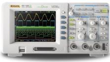 Sooner or later, any novice electronics engineer, if he does not give up his experiments, will grow to circuits where you need to monitor not just currents and voltages, but the operation of the circuit in dynamics. This is especially often needed in various generators and pulse devices. There is nothing to do without an oscilloscope!
Scary device, huh? A bunch of pens, some buttons, and even the screen and nifiga is not clear what is here and why. Nothing, we’ll fix it now. Now I’ll tell you how to use the oscilloscope.
In fact, everything is simple here - the oscilloscope, roughly speaking, is just ... voltmeter! Only cunning, able to show a change in the shape of the measured voltage ...
About grounding and grounding for "dummies"
 My bitter experience as an electrician allows me to say: If you have the "grounding" done as it should - that is, the shield has a connection point for the "grounding" conductors, and all the plugs and sockets have "grounding" contacts - I envy you, and there’s nothing for you worry.
Grounding Rules
What is the problem, why can not you connect the ground wire to the heating or water pipes?
Actually, in urban conditions, stray currents and other interfering factors are so great that anything can appear on the heating battery. However, the main problem is that the trip current of the circuit breakers is quite large. Accordingly, one of the options for a possible accident is a breakdown of a phase to a case with a leakage current just somewhere on the machine operation boundary, that is, at best 16 amperes. Total, we divide 220v by 16A - we get 15 ohms. Just some thirty meters of pipes, and get 15 ohms. And the current flowed somewhere, in the direction of not sawn wood. But that is no longer important. The important thing is that in the next apartment (up to which 3 meters, and not 30, the voltage on the tap is almost the same 220.), but on, say, the sewer pipe - a real zero, or so.
And now the question is - what will happen to the neighbor if he, sitting in the bathroom (connected to the sewer by opening the cork), touches the tap? Guessed?
The prize is prison. According to the article on violation of electrical safety rules that caused the victim.
Do not forget that you can not do an imitation of the "grounding" circuit, connecting the "zero working" and "zero protective" conductors in the Euro socket, as some "craftsmen" sometimes practice. Such a replacement is extremely dangerous. Cases of burning off the “working zero” in the shield are not uncommon. Thereafter ...
How to make a welding machine from an electric motor
 The idea of producing transformers from electric motor stators was practiced twenty years ago and was popular among home-made ones. By the way, the income brought tangible. For 50-75 Soviet carbovanets, such a product could be disposed of in one to two days. What I did. There were even publications on this subject in The Modeler-Designer and The Inventor and Rationalizer.
A little later there were also publications on welding transformers from LATRs. And if there were no special problems with transformers from LATRs, then with those from engines, the results for self-made ones were very far from the calculated ones. And the reason for this is a lack of knowledge in electrical engineering, and magazines published material hiding all underwater currents.
It was more like an instruction to a young dushman, with landmine recipes. It only remained to shout: “Allahu akbar” or “Banzai” and plug into the outlet. And then, at least, burnt traffic jams, as a maximum - a cord to the electricity meter and a lot of flattering reviews for the inventors and their parents.
Of course, I understood all the reasons for the failures, but I did not want to give out secrets, so as not to breed competitors. And only after I found myself a more interesting income, in the form of electric rods, I began to share information. I was still living in Samara and the opportunity to earn money on fish attracted me much more than groan and sweat over the welders.
So, about transformers. First you need to choose the right motor ...
 Some models of bells or bells have batteries inside the case, others have built-in transformers that reduce the mains voltage of 220 V (or 230 V) to small values necessary for this type of electrical appliance. In many models, both power methods can be used. Most of them use two or four batteries with a voltage of 1.5 V, and some use one battery with a voltage of 4.5 V.
Commercially available transformers for doorbell circuitry typically have three pairs of 3, 5, and 8 V pins (contacts) that can be used in various types of bells. As a rule, 3 and 5 V are used in calls and buzzer, and 8 V is suitable for many bell variants.
However, some bell models require a higher voltage, and they need transformers with 4, 8, and 12 V outputs. The bell transformer must be designed so that the mains voltage cannot reach the low voltage windings.
Batteries, buttons and bells are connected by a two-core insulated “bell wire”. This thin wire is usually laid on the surface and fastened with small piercing brackets. The bell wire also connects the bell and button to a transformer.
Connect the double-insulated bell transformer to the junction box or ceiling socket of the lighting circuit with a two-wire rigid wire ...
