Baby boy and electrical outlet
 A nozzle made with your hands will protect the small child from electric shock.
It is known that children like to touch sockets with their fingers, insert cloves and scissors there. They probably subconsciously try to imitate their parents in this way. In this case, the child’s hands may be exposed to electric current. And needles, small pins, paper clips, screws, screws and nails can remain inside the electrical outlet and cause a short circuit in it. At the same time, a short circuit can be a source of fire in your apartment. To prevent this, of course, you can install a factory outlet with a fuse, or you can make such protection yourself.
To do this, it is necessary to prepare a protective disk made of thin plastic with a thickness of 2-3 mm, dimensions along the inner diameter of the socket for the plug in the socket. Drill two holes for the plug in our disk - false panel ...
How to replace an electric meter without disconnecting electricity consumers
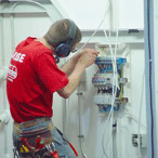
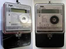 Electric meters are subject to periodic verification. According to the "Rules for the Use of Electric and Thermal Energy", the inter-calibration interval should be no more than four years for devices used in the ASKUE system (we will discuss this system later) and at least eight years for local electricity meters. Therefore, according to these standards, electricity meters must be periodically dismantled and attorneys installed instead.
It would seem that there is nothing complicated about this. But imagine that you need to replace the electric meter on a feeder, the disconnection of which is problematic for several reasons. For example, due to the continuity of the process.
Is it possible to make sure that a replacement is made without disconnecting consumers and at the same time in strict accordance with the Safety Rules? ...
Installation and installation of electric meters
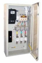 Before installing the meter, it is necessary to draw up a wiring diagram. The meter prepared for installation is subjected to external inspection. The counter is cleared of dirt and dust; the suitability of the meter is checked by its type and technical characteristics; the presence of state verification seals on the screws securing the casing is checked.
The seals indicate the year and quarter of state verification, as well as the stigma of the state witness. Installed three-phase meters must have state verification seals no more than 12 months old, the integrity of the casing and glass, the presence of all screws in the junction box, the presence of fixing screws with holes for sealing in the lid of the junction box, the presence of a circuit on its inside should be checked. Here I want to emphasize the following point - purely by chance on the counter there may be a cover from another type of device, therefore I strongly advise you not to navigate only with this circuit!
The counter, like any measuring device, should be protected from shock and shock. They can cause damage to the supports, curvature of the axis and, as a result, an increase in error and even mashing of the moving part. Before installing the meter, you must ...
The most common schemes for switching on single-phase and three-phase electric meters
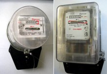 In this article we will consider the basic schemes for switching on single-phase and three-phase electric meters. I want to note right away that the switching circuits of induction and electronic electric meters are absolutely identical.
The mounting holes for fixing both types of electric meters should also be exactly the same, however, some manufacturers do not always adhere to this requirement, therefore, sometimes there may be problems installing an electronic electric meter instead of induction in terms of mounting on the panel.
The clamps of the current windings of electric meters are indicated by the letters G (generator) and N (load). In this case, the generator clamp corresponds to the beginning of the winding, and the load clip corresponds to its end.
When connecting the meter, it is necessary to ensure that the current through the current windings passes from their beginnings to the ends. To do this, the wires from the power supply side must be connected to the generator terminals (terminals G) of the windings, and the wires extending from the meter to the load side must be connected to the load terminals (terminals H) ...
How to determine the number of turns of transformer windings
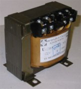 When the type or type of transformer data is not known, the number of turns of each winding can be determined using a multimeter.
Using an ohmmeter, determine the location of the terminals of all the transformer windings. If there are gaps between the coil and the magnetic circuit, an additional winding is wound over the windings with a thin wire. The more turns the winding has, the more accurate the measurement results will be.
If there is no space on the transformer coil for an additional winding, then instead of an additional winding, you can use part of the outer winding. To do this, carefully open the outer insulation layer of the coil to gain access to the last layer of the winding, made, as usual, turn to turn. A number of turns are counted from the end of this winding in the “naked” layer. Carefully clean the enamel of the last counted turn.
When measuring, one probe of the voltmeter is connected to the end of the winding, the needle is clamped to the other probe. An ohmmeter measures the resistance of all windings, a winding with high resistance is primary.
In the case when there are still windings with high resistance, one of the windings with low resistance is taken as the primary one and a low alternating voltage is applied to it, for example ...
How to repair a choke for a fluorescent lamp
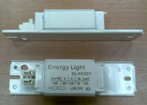 In the article, the author shares his experience in the restoration of chokes, which are part of industrial devices for supplying linear fluorescent lamps. Prices for these chokes can be higher than for fluorescent lamps. Unfortunately, acquiring the required copy of the inductor can be difficult, especially in the "outback. Yes, and it is not always possible to place the product that is offered on the market in the chandelier (shade) of a fluorescent lamp. It can be cheaper, easier and faster to restore an old defective inductor than acquiring new.
Tricky probe instead of a tester
 I borrowed this sampler circuit from N. Shilo (Ukraine) in 1984. I don’t know who its author is, but many years of experience using this sampler show that it would be useful to share experience.
In my specialty, I deal with electric drives, as well as control circuits for automatic lines, etc. I believe that in nine out of ten cases this probe replaces a regular tester. The probe allows you to evaluate the magnitude and sign ("+", "-", "~") of the voltage in several ranges: up to 36 V,> 36 V,> 110 V,> 220 V, 380 V, as well as ringing electrical circuits, such as the contacts of relays, starters, their coils, incandescent lamps, p-n transitions, LEDs, etc., i.e. almost everything that an electrician encounters in the course of his work (with the exception of measuring current).
In the diagram, the switches SA1 and SA2 are shown in a non-pressed state, i.e. in the position of the voltmeter. The magnitude of the voltage can be judged by the number of LEDs in the line VD3 ... VD6, VD1 and VD2 indicate the polarity. Resistor R2 must be made of two or three identical resistors connected in series with a total resistance of 27 ... 30 kOhm. The pressed switch SA2 turns the probe into a classic dial, i.e. battery plus a light bulb. If you press both switches SA1 and SA2, then you can check the circuit in two resistance ranges: - the first range is from 1 MOhm and above to ~ 1.5 kOhm (VD15 is on); - second range - from 1 kOhm to 0 (VD15 and VD16 are lit) ...
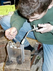 The problems associated with brazing aluminum are explained by the fact that the surface of this metal is covered with a thin, flexible and very strong oxide film - Al2O3. It is not possible to remove it by mechanical methods, because when a clean surface of aluminum comes into contact with air or water, it instantly again becomes covered with an oxide film. Conventional fluxes do not dissolve oxide.
For mechanical cleaning of oxide, it is recommended to clean the surface under a film of oil, but in this case the oil must be completely dehydrated, for which it needs to be heated for some time at a temperature of 150-200 ° C.
It is recommended to use mineral oils, preferably vacuum VM-1, VM-4.
There are tips for using rifle alkaline oil for this purpose, how effective it is is difficult to say, because probably if the oil contains alkali, then water too. There are soldering irons in which a steel scraper is mounted on the sting for cleaning.
It is also proposed to clean the surface with coarse iron filings, which are rubbed over the surface under a layer of oil or rosin with a soldering iron tip, the filings here act as an abrasive, tinning occurs at the same time, I tried this method, the connection is weak, apparently due to spot tinning aluminum.
Probably a more reliable soldering can be obtained by tinning aluminum over a sublayer of copper electrolytically deposited on the surface of aluminum. Perhaps, for the same purpose, a sublayer of zinc can be used, which is applied in the same way as in the aluminum chromium recipe. The oxide film is more reliably removed by ...
