Categories: Featured Articles » Electrician Secrets
Number of views: 390289
Comments on the article: 29

How to choose a cable section - designer tips


The article considers the main criteria for choosing a cable section, gives examples of calculations.
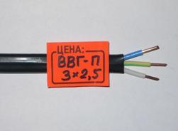
How to choose cable sections - designer tipsIn markets, you can often see hand-written signs indicating which cable must be purchased by the buyer depending on the expected load current. Do not believe these signs, as they mislead you. The cable cross-section is selected not only by operating current, but also by several parameters.

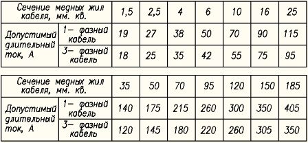
First of all, it must be borne in mind that when using a cable at the limit of its capabilities, the cable cores heat up several tens of degrees. The current values ​​shown in Figure 1 suggest heating of the cable cores to 65 degrees at an ambient temperature of 25 degrees. If several cables are laid in one pipe or tray, then due to their mutual heating (each cable heats all other cables), the maximum allowable current is reduced by 10 - 30 percent.

Also, the maximum possible current decreases at elevated ambient temperatures. Therefore, in a group network (a network from shields to fixtures, plug sockets and other electrical receivers), cables are usually used at currents not exceeding 0.6 - 0.7 from the values ​​shown in Figure 1.

Permissible continuous current of cables with copper conductors

Fig. 1. Permissible continuous current of cables with copper conductors

On this basis, the widespread use of circuit breakers with a rated current of 25A to protect the outlet networks laid with cables with copper conductors with a cross section of 2.5 mm2 is a danger. Tables of reducing coefficients depending on the temperature and the number of cables in one tray can be found in the Electrical Installation Rules (PUE).

Additional restrictions arise when the cable is long. At the same time, voltage losses in the cable can reach unacceptable values. As a rule, when calculating the cables, the maximum losses in the line are no more than 5%. Losses are not difficult to calculate if you know the resistance value of the cable cores and the estimated load current. But usually for calculation of losses tables of dependence of losses on the moment of loading are used. The load moment is calculated as the product of the cable length in meters and power in kilowatts.


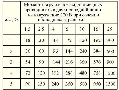
The data for calculating losses at a single-phase voltage of 220 V are shown in table1. For example, for a cable with copper conductors with a cross-section of 2.5 mm2 with a cable length of 30 meters and a load power of 3 kW, the load moment is 30x3 = 90, and the loss will be 3%. If the calculated loss value exceeds 5%, then it is necessary to choose a cable with a larger cross section.

Table 1. The load moment, kW x m, for copper conductors in a two-wire line at a voltage of 220 V for a given section of the conductor

Load moment, kWhm, for copper conductors in a two-wire line at a voltage of 220 V for a given section of the conductor

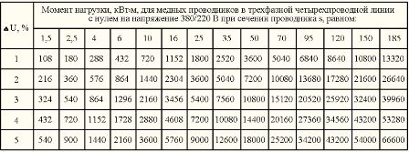
According to table 2, you can determine the loss in a three-phase line. Comparing tables 1 and 2, it can be noted that in a three-phase line with copper conductors with a cross section of 2.5 mm2, a loss of 3% corresponds to a six times greater load moment.

A triple increase in the load moment occurs due to the distribution of the load power in three phases, and a double increase due to the fact that the current in the neutral conductor is zero in a three-phase network with a symmetrical load (identical currents in phase conductors). With an unbalanced load, losses in the cable increase, which must be taken into account when choosing the cable section.

Table 2. The load moment, kW x m, for copper conductors in a three-phase four-wire line with zero voltage of 380/220 V for a given section of the conductor (to enlarge the table, click on the figure)

Load moment, kW x m, for copper conductors in a three-phase four-wire line with zero voltage of 380/220 V for a given section of the conductor

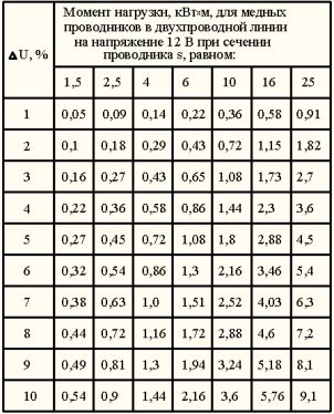
Losses in the cable are strongly affected when using low-voltage, for example, halogen lamps. This is understandable: if 3 Volts drops on the phase and neutral conductors, then at a voltage of 220 V we most likely will not notice this, and at a voltage of 12 V the voltage on the lamp will drop by half to 6 V.That is why transformers for powering halogen lamps must be brought as close as possible to the lamps. For example, with a cable length of 4.5 meters with a cross section of 2.5 mm2 and a load of 0.1 kW (two lamps of 50 W each), the load moment is 0.45, which corresponds to a loss of 5% (Table 3).

Table 3. The load moment, kW x m, for copper conductors in a two-wire line at a voltage of 12 V for a given section of the conductor

Load moment, kW x m, for copper conductors in a two-wire line at a voltage of 12 V for a given section of the conductor

The above tables do not take into account the increase in the resistance of conductors from heating due to the flow of current through them. Therefore, if the cable is used at currents of 0.5 or more of the maximum allowable cable current of a given section, then an amendment must be made. In the simplest case, if you expect to receive losses of no more than 5%, then calculate the cross section based on the losses of 4%. Also, losses can increase with a large number of cable conductor connections.

Cables with aluminum conductors have a resistance of 1.7 times greater compared to cables with copper conductors, respectively, and losses in them are 1.7 times greater.

The second limiting factor for large cable lengths is the excess of the permissible value of the phase-zero circuit resistance. To protect cables from overloads and short circuits, as a rule, use circuit breakers with a combined release. Such switches have thermal and electromagnetic releases.

The electromagnetic release provides instantaneous (tenths and even hundredths of a second) shutdown of the emergency section of the network during a short circuit. For example, a circuit breaker labeled C25 has a thermal release of 25 A and an electromagnetic release of 250A. Circuit breakers of group "C" have a multiplicity of breaking current of the electromagnetic release to thermal from 5 to 10. But at calculation of the line for short circuit current the maximum value is taken.

The general resistance of the phase-zero circuit includes: the resistance of the step-down transformer of the transformer substation, the resistance of the cable from the substation to the input distribution device (ASU) of the building, the resistance of the cable laid from the ASU to the switchgear (RU) and the cable resistance of the group line itself, the cross section of which is necessary to determine.

If the line has a large number of cable conductor connections, for example, a group line of a large number of fixtures connected by a loop, then the resistance of contact connections must also be taken into account. For very accurate calculations, the arc resistance at the fault location is taken into account.

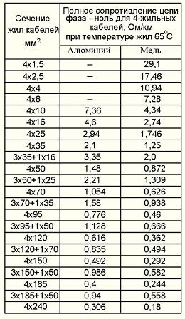
The impedance of the phase-zero circuit for four-wire cables is shown in Table 4. The table takes into account the resistances of both phase and neutral conductors. Resistance values ​​are given at a cable core temperature of 65 degrees. The table is also valid for two-wire lines.

Table 4. The total resistance of the phase-zero circuit for 4-core cables, Ohm / km at a core temperature of 65aboutFROM

The total resistance of the phase-zero circuit for 4-core cables, Ohm / km at a core temperature of 65 ° C

In urban transformer substations, as a rule, transformers with a capacity of 630 kV are installed. And more, having an output impedance Rtp of less than 0.1 Ohm. In rural areas, transformers of 160 - 250 kV can be used. And having an output resistance of the order of 0.15 Ohms, and even transformers at 40 - 100 kV. And having an output impedance of 0.65 - 0.25 Ohms.

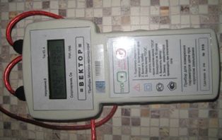
Power supply cables from urban transformer substations to the ASG of houses are usually used with aluminum conductors with a cross-section of phase conductors of at least 70 - 120 mm2. When the length of these lines is less than 200 meters, the resistance of the phase-zero circuit of the supply cable (Rpc) can be taken equal to 0.3 Ohm. For a more accurate calculation, you need to know the length and cross section of the cable, or measure this resistance. One of the instruments for such measurements (the Vector instrument) is shown in Fig. 2.

The device for measuring the resistance of the phase-zero circuit

Fig. 2. The device for measuring the resistance of the phase-zero circuit "Vector"

The resistance of the line must be such that with a short circuit the current in the circuit is guaranteed to exceed the operating current of the electromagnetic release.Accordingly, for the circuit breaker C25, the short circuit current in the line should exceed 1.15 × 10 × 25 = 287 A, here 1.15 is the safety factor. Therefore, the phase-zero circuit resistance for the C25 circuit breaker should be no more than 220V / 287A = 0.76 Ohm. Accordingly, for a circuit breaker C16, the circuit resistance should not exceed 220V / 1.15x160A = 1.19 Ohms and for a circuit breaker C10 - no more than 220V / 1.15x100 = 1.91 Ohms.

Thus, for an urban apartment building, taking Rtp = 0.1 Ohm; Rpc = 0.3 Ohm when using a cable with copper conductors with a cross section of 2.5 mm2 protected by a C16 circuit breaker in the outlet network, the cable resistance Rgr (phase and neutral conductors) should not exceed Rgr = 1.19 Ohm - Rtp - Rpk = 1.19 - 0.1 - 0.3 = 0.79 Ohms. According to table 4 we find its length - 0.79 / 17.46 = 0.045 km, or 45 meters. For most apartments this length is enough.

When using a C25 circuit breaker to protect a cable with a cross section of 2.5 mm2, the circuit resistance should be less than 0.76 - 0.4 = 0.36 Ohm, which corresponds to a maximum cable length of 0.36 / 17.46 = 0.02 km, or 20 meters.

When using a C10 circuit breaker to protect a group lighting line made with a cable with 1.5 mm2 copper conductors, we get the maximum allowable cable resistance of 1.91 - 0.4 = 1.51 Ohms, which corresponds to a maximum cable length of 1.51 / 29, 1 = 0.052 km, or 52 meters. If you protect such a line with a C16 circuit breaker, then the maximum line length will be 0.79 / 29.1 = 0.027 km, or 27 meters.

See also:Why do phase-zero loop resistance measurements be performed by professionals and not hackers

Victor Ch

See also at bgv.electricianexp.com:

  • How to calculate cable for extension cable
  • How to find out how much power a cable or wire can withstand
  • The cross-sectional area of ​​wires and cables, depending on the current strength, the calculation is necessary ...
  • What is cable insulation resistance and its norms
  • Is it worth replacing a circuit breaker if it "knocks out"?

  •  
     
    Comments:

    # 1 wrote: | [quote]


    Thanks. The article is very helpful. Of course, if the above calculations are reliable.

     
    Comments:

    # 2 wrote: | [quote]


    siGis,
    The calculations are reliable. If you find an inaccuracy, write immediately.

     
    Comments:

    # 3 wrote: | [quote]


    Are the calculations reliable for the guest? And for wires, cables made on that?

     
    Comments:

    # 4 wrote: Daddy | [quote]


    1. If you really measure the cross-section of the sold wires, then the real cross-section of the wire will be 10 .. 40% lower than declared (depending on the greed of the manufacturer and seller).

    2. In military products, a current of not more than 8A per 1 sq. Mm of wire cross-section is laid.

    3.Japanese in their recommendation for the installation of air conditioners advise choosing a wire at a rate of 6A per 1 sq. Mm.

     
    Comments:

    # 5 wrote: Stepan | [quote]


    It is absolutely incorrect to calculate the phase-zero loop, because it is impossible to determine the resistances of a cable supplying a house or an overhead line with all couplings and transitional resistances, therefore it is only necessary to use devices.

     
    Comments:

    # 6 wrote: Victor Ch | [quote]


    Stepan,
    Devices are not enough. You can measure the phase-zero loop in the ASU, in the floor board. And what to do with a group line that has not yet been laid? To count.

     
    Comments:

    # 7 wrote: Alexei | [quote]


    Great article. Almost all aspects and dangers of using conductors of insufficient cross section are briefly but intelligibly described.

    Each seller to understand the article and memorize! It is very difficult to explain to people that all the signs in the stores are very conditional and approximate data.

     
    Comments:

    # 8 wrote: | [quote]


    I read it with great pleasure, all that is needed in one place.

     
    Comments:

    # 9 wrote: | [quote]


    Good, practical article

     
    Comments:

    # 10 wrote: | [quote]


    Helpful information. But in the country house, I spread all the wiring for outlets with a section of 2.5, lighting 1.5. When connecting a 3-phase network, is it possible to abandon everything in one phase?

     
    Comments:

    # 11 wrote: | [quote]


    This article is very good and useful, especially for those who want to learn at least the most elementary!

     
    Comments:

    # 12 wrote: | [quote]


    but I did not find a solution to my question in the article: the house of 1957, after repair, remained flat sticking aluminum wire sticking out of the wall at a height of 2 meters in each core, what should I do with it, how to use it, can I connect a flashlight?

     
    Comments:

    # 13 wrote: | [quote]


    For Ira: two phases - it can be

    1. Breakage of the zero wire in the switchboard or inside the apartment (house). Then two options are possible:

    1.1 bgv.electricianexp.com/main/sekrety/498-dve-fazy-v-vashey-rozetke-220-volt-eto-bolee-real
    no-chem-vy-dumaete.html - this is if there is no main "zero"

    1.2 if zero inside the apartment is cut off, then nothing will work from such a network - the phase is the same.

    2. It is unlikely, but it can be, these are two phases of a three-phase network. Then between them 380 volts and connecting a household lamp is not recommended.

    A multimeter armed with a competent electrician will help to resolve the issue ... that is, vice versa.

     
    Comments:

    # 14 wrote: | [quote]


    Daddy,
    Hello, my name is Alexander, I want to say that the seller’s greed is for sure, you’ll go to the store, there is a packed bay - VVG 3 * 2.5 (GOST), the cost is 15 rubles / meter. I went after him, in a week, I needed 25 meters to set up the rooms (input). I’m telling you this one, a three-core 2.5 square meter — 25 meters, I bought it and went home, measured it with a caliper, counted it, looked at it, but THIS turned out to be 1.5 square, 3 core. The real price is 10 rubles \ m. So now I’m thinking what should I do with it, and I’m wondering how the section can jump like this (from 2.5 to 4 squares, the latter being sold as 10 squares). So live after such repairs as on a powder keg. At least for the cable, with a vernier caliper go + calculator. THERE IS SO OUR PEOPLE IN KAZAKHSTAN DISCUSSED, YES AND BEGINNING ELECTRICIANS WILL GO! BAD !!!

     
    Comments:

    # 15 wrote: | [quote]


    great article!

     
    Comments:

    # 16 wrote: | [quote]


    Thank you for the article. In the shops, it’s really not that section indicated, he flew by this summer, my old koment “Alexander from Pavlodar” which is higher.

     
    Comments:

    # 17 wrote: | [quote]


    Daddy, how are you going to measure the cross-section as a ram?

     
    Comments:

    # 18 wrote: | [quote]


    Thank you, an interesting article to replenish knowledge in electricity, reprinted all the tables to navigate. Ah !, the section of veins in the store is fooled, I always take the section an order of magnitude higher than 2.5 square meters, corresponds to 1.5 square meters. etc.

     
    Comments:

    # 19 wrote: | [quote]


    When using a C25 circuit breaker to protect a cable with a cross section of 2.5 mm2, the circuit resistance should be less than 0.76 - 0,4 = 0.36 Ohms, which corresponds to a maximum cable length of 0.36 / 17.46 = 0.02 km, or 20 meters. The question is, what kind of figure is this: 0,4

     
    Comments:

    # 20 wrote: Monkey | [quote]


    Tell the program to makepayment wire and cable sections by currentpower. Thanks!

     
    Comments:

    # 21 wrote: MaksimovM | [quote]


    Alexander, the caliper measures the diameter of the cable, and then, using the known diameter, we find the cross-sectional area of ​​the cable. To do this, use the formula Scr= (pd2)/4 where P = 3.14, and d is the measured diameter of the cable core (wire).

     
    Comments:

    # 22 wrote: MaksimovM | [quote]


    Having studied a lot of electrical literature, I came to the conclusion that the most optimal ratio of load to cable cross-section for apartment wiring is 10 amperes per 1 sq. mm for copper, and 8 amperes per 1 sq. mm for aluminum cable. I do not bother with long (and, in my opinion, not relevant for domestic purposes) calculations of the cable section, but I calculate the required cable section for laying the wiring according to the above ratios.

     
    Comments:

    # 23 wrote: | [quote]


    I want to say that manufacturers of cable products save not only on quantity (cross-section does not correspond to reality) but also on quality.With the union, if the cable was copper, then it was copper, but now some alloys are incomprehensible, so this should also be taken into account in the calculations. They do not withstand the load and the short-circuit currents also hold very poorly. The Soviet VVGng cable holds at the limit of 7 kW, the current one can not stand so much. Under the USSR, everything was done according to guests and standards. Now, when designing a cable, they are calculating with a large margin of safety and my opinion is that saving on apartment wiring is not worth more.

     
    Comments:

    # 24 wrote: Alexei | [quote]


    Any TU for cables can not contradict GOST, the parameters can differ only in the direction of tightening requirements. TU generally only reflect the capabilities of the production line of a particular enterprise. When buying cable products, be sure to pay attention to the marking, which should be printed on the cable itself with the manufacturer's factory, markings (for example, VVGng (A) -LS), cross-section, year of manufacture, technical specifications (GOST). It is better to know reliable suppliers (for example, SevKabel), there are a lot of counterfeit products on the market. It is better to use a cable for internal wiring in the apartment at least 3x2.5 for copper, to avoid the use of aluminum in general.

    When choosing a cable, it is worth checking for the condition of non-ignition (in accordance with the Circular Roselectromontage)

     
    Comments:

    # 25 wrote: | [quote]


    There is a good program which I use where you can pick up a wire by current load, etc. Electrician 7.7

     
    Comments:

    # 26 wrote: Michael | [quote]


    I am often asked how to calculate the cable cross-section by power. Now I will give this article to everyone. It’s very well said that to choose the cable section, you need to consider not only power. Sometimes it’s very easy to explain. People are simply looking for simple solutions, but not everything simple is ingenious.

     
    Comments:

    # 27 wrote: | [quote]


    Article zer gud. But in our country, due to the specifics, it is often necessary to use hard cables and wires, not with a monolithic core, but flexible with a multi-wire core (vibration, crane, mobile, then ..) to connect the equipment. How correct is it to use the data of correction factors and tables in this case?

     
    Comments:

    # 28 wrote: | [quote]


    Is it possible to use a copper cable for external wiring, if the apartment has all aluminum wiring? I ask, because once an electrician said something about it ... that it is important to know what kind of wiring you have.

     
    Comments:

    # 29 wrote: Sergei | [quote]


    Good afternoon! Consult how the temperature on the conductor is calculated at a current for cable 2.5mm2.