Categories: Featured Articles » Electrician Secrets
Number of views: 15765
Comments on the article: 0
How to perform grounding calculation for the contour of a private residential building
Owners of individual houses and cottages are increasingly beginning to understand that the use of electricity not only greatly facilitates the fulfillment of everyday household needs, but also poses certain risks to humans. In life, there is always the possibility of an emergency, which can lead to electrical injury.
Electrical safety of a separate building requires constant close attention from the owner. One of the issues of its maintenance is the operation of an individual ground loop, which must not only be created according to a certain methodology, but also correctly selected design, having performed a reliable calculation of all its elements.
We’ll make a reservation right away that anyone who is familiar with the basics of electrical engineering can do it yourself. To do this, below is the methodology for its implementation.
However, it is of a recommendatory, fact-finding nature and requires clarification of the result obtained in a specialized laboratory, which has a license for the right to conduct an examination by trained personnel of designers who periodically confirm their qualifications by passing examinations in inspecting state bodies.
The choice of grounding design for calculation
In the electrical circuit of buildings for various purposes, a large number of different types of grounding devices work. Among them, products with:
-
single deep earthing switch;
-
several electrodes of modular type of vertical arrangement;
-
electrolytic grounding of horizontal orientation.
The latter design does not yet have such widespread popularity as the first two listed, but it may well compete with them and act as an alternative.
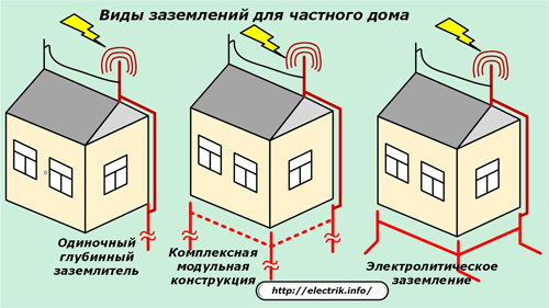
A preliminary calculation of the electrical characteristics of each model will help determine the most suitable type of grounding and make it your choice for further installation, commissioning, operation.
Briefly on examples, consider the methodology for their calculation.
Calculation of ground loops for residential buildings
Appointment
The calculation helps to analyze the dimensions and shape of the created circuit to ensure acceptable electrical resistance to the emergency current, which is removed from the house to the ground potential.
Grounding is designed to reduce the voltage of human touch to a safe value due to the spreading of unacceptable currents from it and the redistribution of dangerous potentials.
For residential buildings, the loop resistance should not exceed 8 Ohms when operating a single-phase 220 volt network and 4 Ohms for a three-phase 380.
Factors Affecting Loop Calculation
The magnitude of the electrical grounding resistance depends on:
1. soil conductivity;
2. used in the construction of metal;
3. the shape and number of electrodes;
4. distance between grounding conductors;
5. the depth of the contour.
Soil characteristics
To take into account their influence on the flow of currents, the term “Soil resistivity” is used, the unit of which is chosen to be “Ohm ∙ m”. It is denoted by the Latin letter ρ. This indicator depends on many factors, including soil moisture and its composition, varies within certain limits, even taking into account weather conditions.
The value of soil resistivity is determined by measuring on the ground, and its average values for preliminary approximate calculations are summarized in tables. Grounding electrodes are buried 0.7 meters or more into the ground to reduce climate impact.
Compare the effect of soil composition, humidity, temperature of the working environment on the value of this indicator can be based on the proposed table.
Table of approximate resistivity values for soils and water
Earthing metal
For the manufacture of loop electrodes, usually choose:
-
stainless alloy steel grades;
-
conventional steel alloys used for the manufacture of pipes, corners, rods;
-
copper plated steel alloys.
The magnitude of their conductivity is easy to find in technical manuals.
Loop parameters affecting the calculation of grounding resistance R
In addition to the soil resistivity ρ, the analysis must take into account:
1. electrode length L;
2. its diameter D;
3. the depth of the electrode from the soil surface to its middle T;
4. The total number of electrodes N;
5. Ki utilization factor;
6. electrolyte content in soil C.
Methods for calculating grounding from a single deep electrode
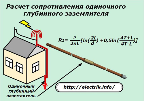
The grounding device can be one-piece or created from a prefabricated structure made by welding or on the basis of a threaded connection of working parts.
To calculate its electrical resistance, use the formula shown in the picture.
Methods for calculating grounding from several buried electrodes
The electrical resistance of a single electrode is determined by the previously given formula, and the ratio shown in the next picture is used to calculate their total effect on the final result.
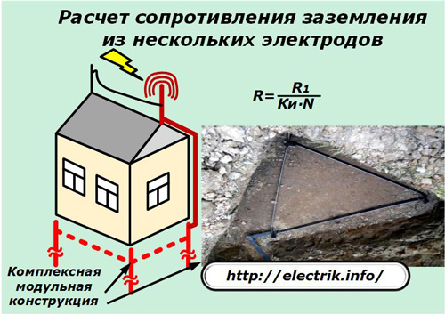
The electrodes may be in a line or form a triangle or other symmetrical geometric shape.
Methods for calculating grounding from electrolytic grounding conductors
For its implementation, the same principles are used as in calculating the resistance of horizontal electrodes made in the form of a conventional pipe. Only the effect of electrolyte on the surrounding soil is taken into account. For this, a correction of coefficient C is introduced. It can vary under different conditions from 0.05 to 0.5.
The formula for calculating the resistance is presented in the picture.
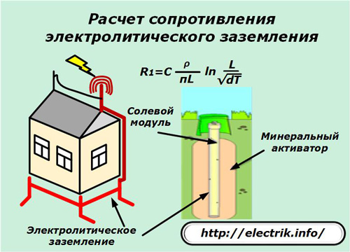
Electrolytic grounding is made in the form of a horizontal section of a hollow pipe made of stainless alloy steel or copper alloys that are resistant to corrosion processes. Through it, the soil is saturated through electrodes with mineral salts that have electrolytic properties.
Salts falling into the soil are converted under the influence of soil moisture into an electrolyte, which:
1. improves the conductive properties of the soil;
2. reduces the freezing temperature of the soil near the electrode and thereby further reduces the electrical resistance of the ground loop.
An effective method of increasing the operability of such structures is the use of activators - special aggregates with reduced resistivity. Their placement on the outside of the electrode reduces the transition resistance in the direction from the ground electrode to the ground and increases the surface area with which the current transfer from the electrode occurs.
A characteristic feature of such structures is that the coefficient C gradually decreases over time: slow penetration of the electrolyte into the thickness of the soil and an increase in its volume in it are affected.
The electrolyte gradually leaches the salts of the electrode even in dense soil and lowers the coefficient C from 0.5 to 0.125 within six months after commissioning.
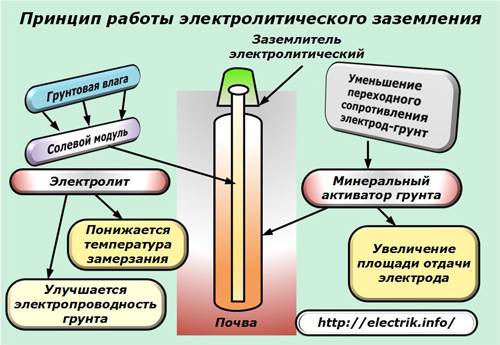
All these features of the operation of electrolytic grounding conductors are more accurately taken into account when calculating by specialists of electrical laboratories.
Simplified Grounding Methodology for the Home Master
It is quite difficult for a home electrician without special knowledge to navigate in all these technologies, which require constant introduction of various corrections and coefficients into the calculation. He is offered a simple and affordable solution based on an already developed computer program.
It is a utility that is simply called: “Electric” and is freely distributed by the developer on a free basis through Internet resources. However, he can be helped by listing a small sum of money that he will spend on improving the working algorithms.
The program for downloading is archived, which occupies 15.9 MB. When installed on a computer, it creates a CU folder located in the “Program Files” directory of drive C and occupies 55.5 MB.
How to calculate the grounding resistance using the program "Electric"
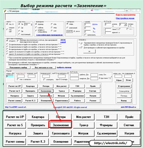
After opening the utility, in the lower part of its window it is necessary to select the “Grounding” calculation mode.
A window opens in which you need to specify the type of design of the grounding device.
Take for example the method No. 1 recommended by the developer and select it with a dot, and then press the "Select" button.
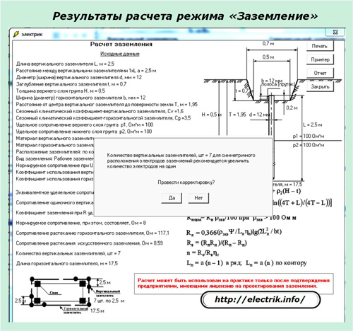
A window will open for inputting the design data of the ground loop we are using and the climatic characteristics of the zone of our residence. We enter the averaged parameters, as shown in the example by additional footnotes, check them and click on the button “Contour calculation”.
The Electric program independently and fairly quickly performs the entire calculation of the ground loop, offers a distribution scheme and the number of grounding conductors, and the geometric dimensions of all structural elements.
It also offers the possibility of further adjusting the calculated characteristics and issued a warning about the need to confirm the results provided by licensed electrical laboratories approved for the design of ground loops.
Without this check, an error in the operation of grounding conductors is possible, which can cause great material damage to the owner and cause electrical injuries to nearby people in the event of an emergency.
Attention! Even the most accurate and correctly performed calculation is not able to exclude errors in installation and connection of the ground loop.
They can only be detected by the laboratory by performing electrical measurements on their specialized equipment.
How to check the quality of the installed ground loop
The correctness of the removal of hazardous currents from the building can be found in only two ways:
1. the occurrence of a real emergency and verification of the consequences of its passage;
2. electrical measurements.
The first method is the most accurate and effective, but it does not allow to eliminate malfunctions and often leads to sad consequences in the presence of errors. In practice, the second method is used: the involvement of specialists from trained electrical units.
What measurements does the laboratory take?
Among uninitiated people, confusion often arises with the basic work and terms performed by such organizations. Therefore, we will focus on their interpretation:
1. measurement of grounding resistance;
2. grounding resistance test;
3. measurement of insulation resistance.
As you can see, all three types of work are very similar in name, but they are performed using different technologies, pursuing their own unique goals.
Earth resistance measurements are intended to identify the quality of the connections of the cases of metal devices that a person can touch with the potential of the earth through a grounding device. In this case, the electrical resistance of this section is measured by special devices of the M416 type or its modern analogues of various modifications.
Ground resistance checks are used to analyze the building's lightning protection status. Its assessment is carried out to determine the resistance of the circuit under the worst operating conditions in order to determine the degree of wear of the entire structure and provide recommendations for its restoration.
For measurement, pin electrodes are installed at several points in the terrain and a potential difference is supplied between them and the circuit.
Insulation resistance measurements imply:
1. determination of the loss tangent of the dielectric insulation layer by conducting high voltage tests;
2. measurements with a megohmmeter.
All these works require special expensive equipment that an ordinary electrician does not use.
See also at bgv.electricianexp.com
:


