Categories: Featured Articles » Electrician Secrets
Number of views: 31257
Comments on the article: 2
Simple ABP circuitry on contactors
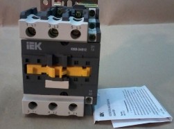 The power supply of any facility should be uninterrupted, but sudden power outages, unfortunately, are not excluded. For such important facilities as hospitals, defense industry facilities, and for many others, accidents at power plants or in power supply networks are in great trouble, for this reason much attention has always been paid and is being paid to the design and construction of backup power supply systems.
Often uninterrupted power supply is ensured by the fact that the consumer has two sources independent from each other, the main and the backup. The main source is the substation line, and the backup is another line that receives power from another power station, or from an autonomous power source, for example, from an industrial generator for liquid fuel or from a battery of batteries, as is often the case in private homes.
If an accident occurs, and the power from the main source ceases to flow to consumers, the backup power supply system automatically connects the backup source, so the consumer is not de-energized, and continues its normal operation as intended. This is the so-called automatic reserve input (ABP). Thanks to the ABP, the consumer instantly switches to backup power, and the accident does not turn into a disaster for the facility.
In reality, the moment of switching turns out to be very responsible, because the automation of the ARV is obliged to provide the whole range of its functions, while preserving the power parameters. At substations and distribution points, multilevel complex schemes for automatic input of a reserve are used, containing both logical and measuring parts, and power, but in this article we will consider two simple ABP circuits on contactors that are suitable for a home or for a small enterprise.
ABP on one contactor
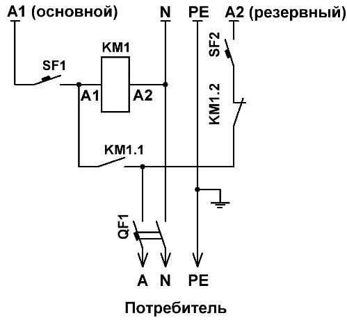
For a single-phase home network, an automatic reserve input circuit made on a single contactor is suitable. The circuit also includes a pair of unipolar circuit breakers and one bipolar.
To turn on the ABP circuit, the SF1 machine is turned on first, then SF2. The main source feeds the coil of the contactor KM1, and the normally open contact KM1.1 goes into a permanently closed state, while the normally closed contact KM1.2 opens.
Phase A1 is fed to the bipolar switch QF1 through the circuit breaker SF1 and through the closed contact KM1.1 of the contactor KM1. When the QF1 is turned on, the consumer receives power from the main source.
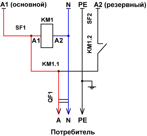
If the voltage of the main source for any reason disappears, the coil of the contactor KM1 ceases to receive power, and the contact KM1.1 opens the consumer's power supply circuit from the main source, while the normally-closed contact KM1.2 closes and the reserve phase A2 through the automata SF2 and QF1 is supplied to the consumer.
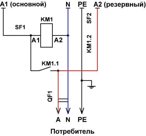
When the main source resumes operation, contactor KM1 will again receive coil power, and contact KM1.1 will close again, and KM1.2 will open. The consumer will again receive power from the main source.
The SF1 switch is used in order to use a backup power source if necessary, it would be possible to manually disconnect the main line, and transfer the power supply to the consumer network to a backup source.
The given circuit is a classic circuit breaker circuit breaker, and during its installation it is enough to take into account the power of the connected consumers, and install the machines and the contactor for the corresponding current. If the automation is designed so that no more than a certain current limit can be taken from the backup source, then only the most necessary equipment can be turned on.
The ABP circuit on one contactor is suitable for those facilities on which there are two independent lines going from the substation, however for home use it is often necessary to completely disconnect both phase and zero to power the home network from its own autonomous source, for this reason the circuit should be slightly modified .
Modified ABP circuit on one contactor
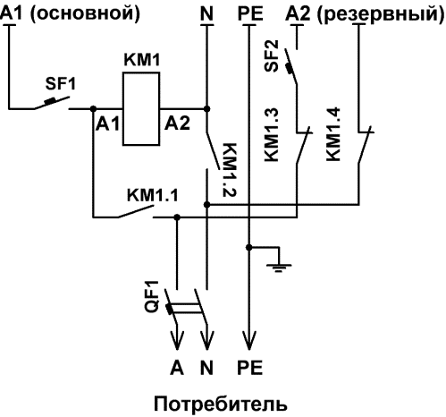
Modification of the circuit differs in that both phase and zero are switched here. This solution is suitable for farms that have their own autonomous source of electricity, and in the event of an accident, the entire home network is disconnected from the main power source, switching to its own autonomous source. Here the ABP circuit is connected after the counter.
The circuit is launched as follows. First, the circuit breaker SF1 is turned on, then SF2. If everything is in order with the main source, the coil of the contactor KM1 receives power, and a pair of normally open contacts KM1.1 and KM1.2 closing, connect the consumer network to the main source. The meter takes into account the supplied electricity. At this time, the normally-closed contacts KM1.3 and KM1.4 are open, so the backup source is disconnected from the network.
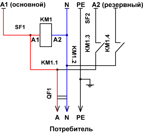
If for some reason the main source stops supplying power to the network, the coil of the contactor KM1 turns off and the contacts KM1.1 and KM1.2 open, disconnecting the phase and zero of the main source from the phase and neutral wires of the consumer network. At the same moment, the contacts KM1.3 and KM1.4 are closed, since the power from the coil controlling their opening has stopped. The backup source is now connected to the consumer network.
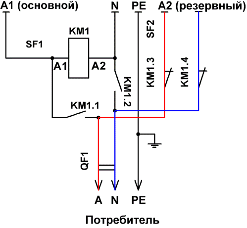
If you want to resume power from the main source manually, then add a button with which the ATS circuit would only come into operation after manually clicking on it.
By pressing the SB1 button, the contact KM1.1 is bypassed, and the coil of the contactor KM1 receives power. Contacts KM1.1 and KM1.2 are closed, connecting the consumer network to the main source. At the same moment, the contacts KM1.3 and KM1.4 open, and the backup source is turned off.
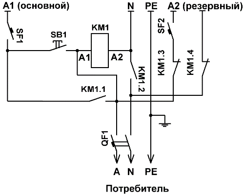
In accordance with individual conditions, the ATS circuit is additionally equipped with a start-up unit that controls the start-up of an autonomous power source, whether it be batteries with an inverter or oil generator.
ATS circuit on two contactors:
We hope that this short article will help you build and run an automatic reserve input circuit at the contactor, and the power supply to your home or small business will become uninterrupted.
An example of using ABP schemes: Connecting the generator to the house network
See also at bgv.electricianexp.com
:
