Categories: Featured Articles » Novice electricians
Number of views: 60979
Comments on the article: 3
How electricity is transmitted to consumers through a 0.4 kV network
 Ways of transferring electrical capacities between high-voltage equipment of energy enterprises are outlined in the previous article. And here we consider the operation of low voltage circuits.
Power lines
High voltage power conversion 0.4 kV network end in transformers with an output voltage of 380/220 volts. From them, electricity is supplied via cable or overhead lines to consumers. Moreover, the cable is most often used where it is impossible to install engineering structures - supports.
Cable lines during operation, they create a reactive load of a capacitive nature in the network, which on long routes greatly affects the quality of electricity, changing the cosφ of the circuit. At short distances, the cable can work as compensation for the loss of electricity from inductive loads created by powerful electric motors.
Aerial power lines used to power remote consumers. The wires of the phases of the overhead lines are spaced apart at a considerable distance. They practically do not create reactance.
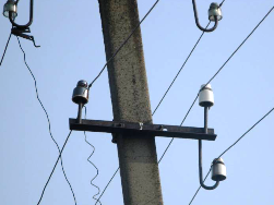
The photo below shows the 0.4kV line support with conventional wires in rural areas. This is an outdated, but rather reliable design.
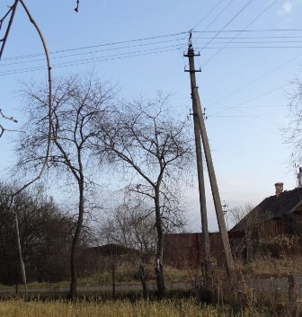
Now in the country there is a massive replacement of wires by self-supporting insulated devices, which are more secure, reduce the theft of electricity. When reconstructing old lines, it is often carried out the replacement of used supports.
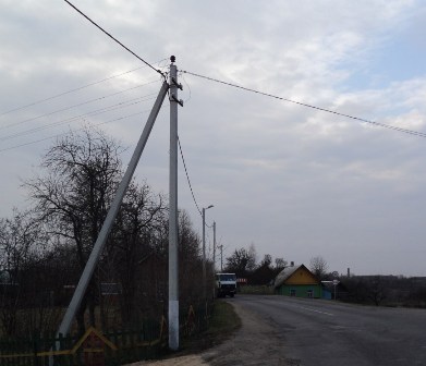
The photo shows an overhead power line with self-supporting wires in the residential sector.
What schemes are used to transfer electricity to a consumer in a 0.4 kV network
The safety of electrical equipment operation largely depends on how it is connected to the ground loop.
During the last century, the country used the consumer nutrition scheme, which is usually denoted by the TN-C indices. This is the cheapest and most dangerous grounding system. They are getting rid of it now, but it is an expensive and lengthy process.
GOST R 50571.2-94 defines grounding systems that classify: IT, TT, TN-S, TN-C, TN-C-S.
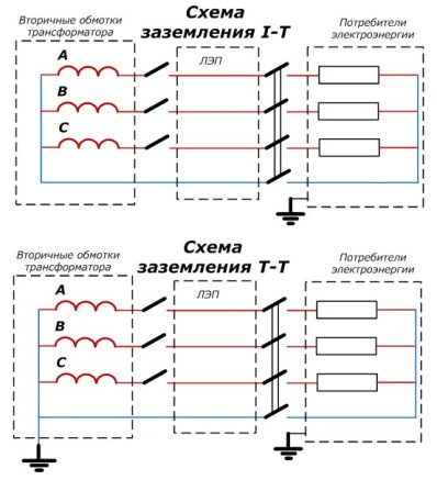
In circuit I-T the neutral wire of the transformer is not grounded and goes directly to the switchgear of consumers of electricity.
TT system The transformer ground terminal is grounded. The enclosures of all power receivers in both circuits according to safety requirements must be connected to the ground loop of the building where they are located.
TN-C system uses the grounding of the instrument cases without connecting them to the ground loop. With this method, in the event of a breakdown in the insulation of the power receiver, a short circuit is created on the case, which is eliminated by circuit breakers or fuses.
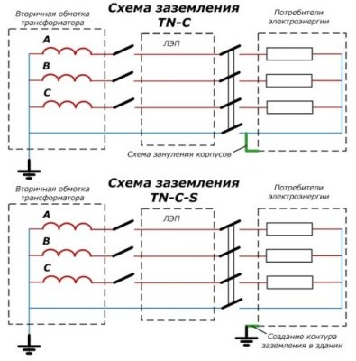
TN-C-S system more secure. She has involved the ground loop of a building in which electrical appliances operate. During damage to their insulation, leakage currents are created to the earth circuit through PE conductors. A circuit failure is disabled by an RCD or by difratomata.
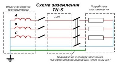
The TN-S system provides for the connection of electrical appliance housings to the grounding circuit of a transformer substation via a separate power transmission line phase. This is the most expensive solution, but the safest. The technical condition of the transformer substation with power lines, including the electrical resistance of the ground loop, is periodically measured by specialists and is always maintained in good condition.
Losses in the transmission of electricity in electrical networks
During the transportation of electrical energy, part of it is spent on related processes, for example, on heating metal conductors, reactive capacity buildingleakage through insulation. They are associated with technology for the transmission of electricity to consumers.
In addition to technological losses, the shortage of electricity can be associated with:
-
with ordinary thefts;
-
errors in metering devices;
-
Incorrect calculations by energy sales units.
International experts have determined that the relative amount of energy lost from the energy generated should be up to 5%. According to statistics, this indicator among the states of Western Europe is limited to 7%, for Russia it ranges from 11 - 13%, and in Belarus - 11.13%.
An analysis of technical losses determined that 78% of them occur in electric networks with a voltage of 110 kV and below, with 33.5% detected in networks of 0.4 ÷ 10 kV.
Reasons for Technological Losses
Rules for choosing a section of current conductors
Thermal emissions of electrical wires are directly related to their electrical resistance. An understated cross section increases it and creates additional energy costs.
When connecting wires, different techniques are used. It should be understood that when two metal surfaces of the current conductors are applied, an electric current flows through the area of their contact. In the place of such contact arises transition resistance.
In linear contacts, it is less than in chiseled ones, but more than in surface ones.
Contact Status
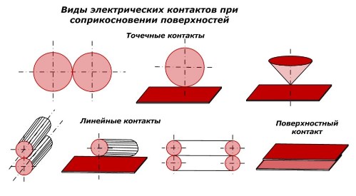
The state of the transition resistance is affected by:
-
type of metal of connected parts;
-
clean contact surfaces and the quality of their processing;
-
the amount of “squeeze” and a number of other factors.
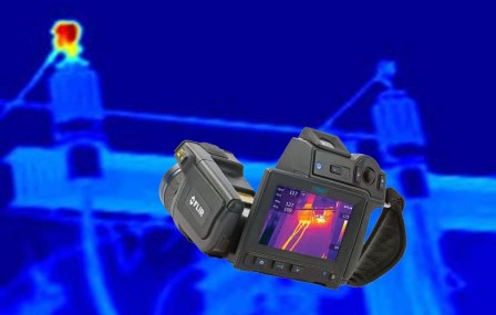
Electric energy during transportation passes through a huge number of contact joints. Maintaining them in good, good condition reduces losses, and careless installation techniques provide costs. To reduce them during operation, periodic preventive maintenance is carried out, and in the intervals between them, a visual observation of thermal emissions inside the contact joints is carried out using thermal imagers.
Reactive Power Loss Compensation
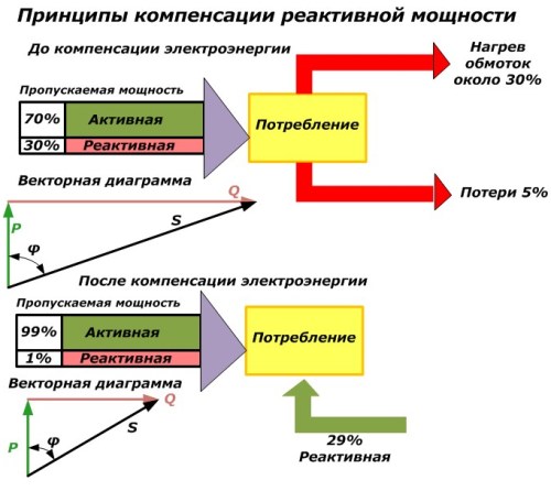
To improve the quality of electric energy transmission, voltage is regulated by compensating devices with the creation of an allowable reserve. With this method, the generated powers are combined with the powers of the compensating devices. The main compensation options are shown in the figure.
Compensation for energy losses is especially relevant in enterprises with a large number of induction motors.
Ways to reduce losses
Enterprises providing electricity transmission services are interested in its quality. It is achieved:
-
reduction in the length of power lines;
-
the use of three-phase lines along the entire length;
-
replacing open wires with self-supporting insulated structures;
-
the use of conductors with the maximum permissible cross-section for the passage of critical loads;
-
reconstruction of transformer equipment into devices with less active and reactive losses;
-
additional installation of 0.4 kV transformers in the circuit, reducing the length of power lines and power losses in them;
-
the introduction of automation and telemechanics;
-
using new measuring instruments with improved metrological characteristics and increasing the accuracy of their processing.
See also at bgv.electricianexp.com
:

