Categories: Featured Articles » Novice electricians
Number of views: 166,352
Comments on the article: 4
Analog sensors: application, methods of connection to the controller
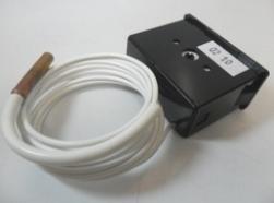 In the process of automation of technological processes for controlling mechanisms and assemblies, one has to deal with measurements of various physical quantities. It can be temperature, pressure and flow rate of a liquid or gas, rotation speed, light intensity, information about the position of parts of mechanisms, and much more. This information is obtained using sensors. Here, first about the position of the parts of the mechanisms.
Discrete sensors
The simplest sensor is a normal mechanical contact: the door was opened - the contact opened, closed - closed. Such a simple sensor, as well as the above algorithm of operation, often used in security alarms. For a mechanism with translational movement, which has two positions, for example, a water valve, two contacts are needed: one contact is closed - the valve is closed, the other is closed - closed.
A more complex translational algorithm has a mechanism for closing the thermoplastic molding machine. Initially, the mold is open, this is the starting position. In this position, finished products are removed from the mold. Next, the worker closes the protective fence and the mold begins to close, a new work cycle begins.
The distance between the halves of the mold is quite large. Therefore, at first the mold moves quickly, and at a certain distance until the halves are closed, the trailer is triggered, the speed of movement is significantly reduced and the mold smoothly closes.
This algorithm allows you to avoid a blow when closing the mold, otherwise it can simply be chopped into small pieces. The same change in speed occurs when the mold is opened. Here, two contact sensors can not do.
Thus, the sensors based on the contact are discrete or binary, have two positions, closed - open or 1 and 0. In other words, we can say that the event occurred or not. In the above example, several points are “captured” by the contacts: the beginning of movement, the point of decrease in speed, the end of movement.
In geometry, a point has no dimensions, just a point and that’s it. It can either be (on a sheet of paper, in the trajectory of movement, as in our case), or it simply does not exist. Therefore, discrete sensors are used to detect points. Maybe a comparison with a point here is not very appropriate, because for practical purposes they use the value of the accuracy of a discrete sensor, and this accuracy is much more than a geometric point.
But mechanical contact alone is an unreliable thing. Therefore, wherever possible, mechanical contacts are replaced by proximity sensors. The simplest option is a reed switch: the magnet is close, the contact is closed. The accuracy of the operation of the reed switch leaves much to be desired, using such sensors is just for determining the position of the doors.
A more complex and accurate option should be considered a variety of proximity sensors. If the metal flag entered the slot, then the sensor worked. As an example of such sensors, the BVK sensors (Non-Contact End Switch) of various series can be cited. The accuracy of operation (stroke differential) of such sensors is 3 millimeters.
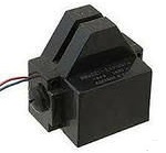
Figure 1. BVK Series Sensor
The supply voltage of the BVK sensors is 24V, the load current is 200mA, which is enough to connect intermediate relays for further coordination with the control circuit. This is how BVK sensors are used in various equipment.
In addition to BVK sensors, sensors of the BTP, KVP, PIP, KVD, FISH types are also used. Each series has several types of sensors, indicated by numbers, for example, BTP-101, BTP-102, BTP-103, BTP-211.
All the mentioned sensors are noncontact discrete; their main purpose is to determine the position of parts of mechanisms and assemblies. Naturally, there are much more of these sensors; you cannot write about all of them in one article. Various contact sensors are still more common and still find widespread use.
The use of analog sensors
In addition to discrete sensors in automation systems, analog sensors are widely used. Their purpose is to obtain information about various physical quantities, and not just like that at all, but in real time. More precisely, the conversion of a physical quantity (pressure, temperature, illumination, flow, voltage, current) into an electrical signal suitable for transmission via communication lines to the controller and its further processing.
Analog sensors are usually located quite far from the controller, which is why they are often called field devices. This term is often used in the technical literature.
An analog sensor typically consists of several parts. The most important part is the sensitive element - sensor. Its purpose is to convert the measured value into an electrical signal. But the signal received from the sensor is usually small. To obtain a signal suitable for amplification, the sensor is most often included in the bridge circuit - Wheatstone bridge.
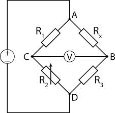
Figure 2. Wheatstone Bridge
The initial purpose of the bridge circuit is an accurate measurement of resistance. A DC source is connected to the diagonal of the AD bridge. A sensitive galvanometer with a midpoint, with zero in the middle of the scale, is connected to another diagonal. To measure the resistance of the resistor Rx by rotating the trimming resistor R2, the bridge must be balanced, the galvanometer arrow must be set to zero.
Deviation of the arrow of the device in one direction or another allows you to determine the direction of rotation of the resistor R2. The value of the measured resistance is determined on a scale combined with the handle of the resistor R2. The equilibrium condition for the bridge is the equality of the ratios R1 / R2 and Rx / R3. In this case, between the points BC, a zero potential difference is obtained, and the current does not flow through the galvanometer V.
The resistance of the resistors R1 and R3 is selected very accurately, their spread should be minimal. Only in this case, even a small imbalance of the bridge causes a noticeable change in the voltage of the BC diagonal. It is this property of the bridge that is used to connect sensitive elements (sensors) of various analog sensors. Well, then everything is simple, a matter of technology.
To use the signal received from the sensor, further processing is required, - amplification and conversion into an output signal suitable for transmission and processing by the control circuit - the controller. Most often, the output signal of analog sensors is current (analog current loop), less often voltage.
Why exactly the current? The fact is that the output stages of analog sensors are based on current sources. This allows you to get rid of the influence on the output signal of the resistance of the connecting lines, to use connecting lines of large length.
Further conversion is quite simple. The current signal is converted to voltage, for which it is enough to pass the current through a resistor of known resistance. The voltage drop across the measuring resistor is obtained according to Ohm's law U = I * R.
For example, for a current of 10 mA on a resistor with a resistance of 100 Ohms, you get a voltage of 10 * 100 = 1000mV, right there is a whole 1 volt! In this case, the output current of the sensor does not depend on the resistance of the connecting wires. Within reasonable limits, of course.
Connection of analog sensors
The voltage received at the measuring resistor can easily be converted to a digital form suitable for input into the controller. Conversion is done using analog-to-digital converters ADC.
Digital data is transmitted to the controller in serial or parallel code.It all depends on the specific switching circuit. A simplified connection diagram of the analog sensor is shown in Figure 3.
Figure 3. Connecting an analog sensor (click on the image to enlarge)
Actuators are connected to the controller, or the controller itself is connected to a computer that is part of the automation system.
Naturally, the analog sensors have a finished design, one of the elements of which is a housing with connecting elements. As an example, Figure 4 shows the appearance of the gauge pressure sensor type Probe-10.
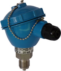
Figure 4. Sensor overpressure Probe-10
At the bottom of the sensor, you can see the connecting thread for connecting to the pipeline, and on the right under the black cover there is a connector for connecting a communication line with the controller.
The threaded connection is sealed with a washer made of annealed copper (included in the scope of delivery of the sensor), and by no means is it used for winding from fum tape or linen. This is done so that when installing the sensor, do not deform the sensor element located inside.
Analog Sensor Outputs
According to the standards, there are three ranges of current signals: 0 ... 5mA, 0 ... 20mA and 4 ... 20mA. What is their difference, and what are the features?
Most often, the dependence of the output current is directly proportional to the measured value, for example, the higher the pressure in the pipe, the greater the current at the output of the sensor. Although inverse switching is sometimes used: a larger value of the output current corresponds to the minimum value of the measured value at the output of the sensor. It all depends on the type of controller used. Some sensors even switch from direct to inverse.
The output signal of the range 0 ... 5mA is very small, and therefore subject to interference. If the signal of such a sensor fluctuates at a constant value of the measured parameter, that is, it is recommended to install a capacitor with a capacitance of 0.1 ... 1 μF parallel to the output of the sensor. More stable is the current signal in the range 0 ... 20mA.
But both of these ranges are not good because the zero at the beginning of the scale does not allow us to unambiguously determine what happened. Or did the measured signal actually take a zero level, which is possible in principle, or simply the communication line was cut off? Therefore, they try to abandon the use of these ranges, if possible.
The signal of analog sensors with an output current in the range of 4 ... 20 mA is considered more reliable. Its noise immunity is quite high, and the lower limit, even if the measured signal has a zero level, will be 4 mA, which allows us to say that the communication line is not broken.
Another good feature of the 4 ... 20mA range is that the sensors can be connected in just two wires, since the sensor itself is powered by this current. This is its current consumption and at the same time a measuring signal.
The power source for sensors in the range 4 ... 20mA is turned on, as shown in Figure 5. At the same time, the Zond-10 sensors, like many others, have a wide range of supply voltage 10 ... 38V according to the passport, although they are most often used stabilized sources with a voltage of 24V.
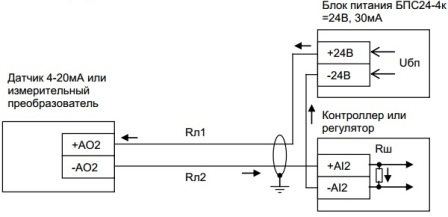
Figure 5. Connecting an analog sensor with an external power source
The following elements and notation are present in this diagram. Rш is the resistor of the measuring shunt, Rl1 and Rl2 are the resistances of communication lines. To increase measurement accuracy, a precision measuring resistor should be used as Rш. The passage of current from the power source is indicated by arrows.
It is easy to see that the output current of the power source passes from the + 24V terminal, through the Rl1 line it reaches the + AO2 sensor terminal, passes through the sensor and through the sensor output terminal - AO2, the Rl2 connecting line, the resistor Rш returns to the -24V power supply terminal. Everything, the circuit is closed, the current flows.
If the controller contains a 24V power supply, then the connection of the sensor or measuring transducer is possible according to the scheme shown in Figure 6.
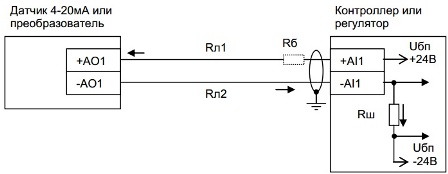
Figure 6. Connecting an analog sensor to a controller with an internal power source
This diagram shows another element - the ballast resistor Rb. Its purpose is to protect the measuring resistor when the communication line is closed or the analog sensor malfunctions. The installation of an RB resistor is optional, although desirable.
In addition to various sensors, measuring transducers, which are often used in automation systems, also have a current output.
Measuring transducer - a device for converting voltage levels, for example, 220V or current of several tens or hundreds of amperes into a current signal of 4 ... 20mA. Here, the conversion of the level of the electric signal simply takes place, and not the representation of some physical quantity (speed, flow rate, pressure) in electrical form.
But the only sensor, as a rule, is not enough. One of the most popular measurements are temperature and pressure measurements. The number of such points in modern production can reach several tens of thousands. Accordingly, the number of sensors is also large. Therefore, several analog sensors are most often connected to one controller at once. Of course, not several thousand at once, it’s good if a dozen are different. Such a connection is shown in Figure 7.
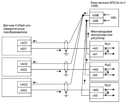
Figure 7. Connecting multiple analog sensors to the controller
This figure shows how a voltage suitable for conversion to a digital code is obtained from a current signal. If there are several such signals, then they are not processed all at once, but are separated by time, multiplexed, otherwise, a separate ADC would have to be put on each channel.
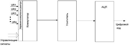
For this purpose, the controller has a circuit switching channels. The functional diagram of the switch is shown in Figure 8.
Figure 8. Analog sensor channels switch (clickable picture)
The signals of the current loop, converted into voltage at the measuring resistor (UR1 ... URn), are fed to the input of the analog switch. The control signals alternately pass one of the signals UR1 ... URn, which are amplified by the amplifier, and are alternately fed to the ADC input. The voltage converted into a digital code is supplied to the controller.
The scheme, of course, is very simplified, but the principle of multiplexing in it is quite possible to consider. This is how the module for inputting analog signals from the MSTS controllers (microprocessor system of hardware) built by the Prolog PC Smolensk was built. The appearance of the MCTC controller is shown in Figure 9.
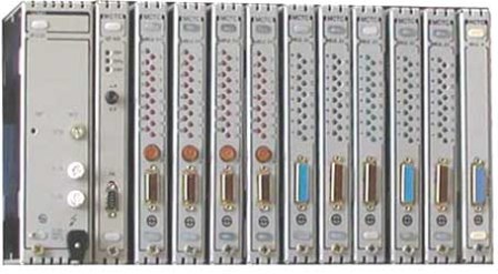
Figure 9. ICTS controller
The release of such controllers has long been discontinued, although in some places far from the best, these controllers still serve. These museum exhibits are replaced by controllers of new models, mainly of imported (Chinese) production.
To connect 4 ... 20mA current sensors, it is recommended to use a two-wire shielded cable with a core cross section of at least 0.5 mm2.
If the controller is mounted in a metal cabinet, it is recommended that shielding braids be connected to the cabinet ground point. The length of the connecting lines can reach more than two kilometers, which is calculated by the corresponding formulas. We won’t consider anything here, but believe me that is so.
New sensors, new controllers
With the advent of new controllers, new HART analog sensors (Highway Addressable Remote Transducer), which translates as "Measuring Transducer Addressable Remotely via the Trunk".
The output signal of the sensor (field device) is an analog current signal in the range 4 ... 20 mA, on which a frequency-modulated (FSK - Frequency Shift Keying) digital communication signal is superimposed.
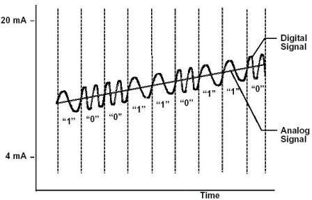
Figure 10. HART Analog Sensor Output
The figure shows an analog signal, and around it, like a snake, a sinusoid coils. This is a frequency-modulated signal.But this is not a digital signal at all, it has yet to be recognized. It is noticeable in the figure that the frequency of the sine wave when transmitting a logical zero is higher (2.2KHz) than when transmitting a unit (1.2KHz). The transmission of these signals is carried out by a current with an amplitude of ± 0.5 mA sinusoidal shape.
It is known that the average value of the sinusoidal signal is zero, therefore, the transmission of digital information does not affect the output current of the sensor 4 ... 20 mA. This mode is used when setting up sensors.
HART communication is done in two ways. In the first case, the standard, only two devices can exchange information on a two-wire line, while the output analog signal 4 ... 20mA depends on the measured value. This mode is used when setting up field devices (sensors).
In the second case, up to 15 sensors can be connected to the two-wire line, the number of which is determined by the parameters of the communication line and the power of the power supply. This is a multi-drop mode. In this mode, each sensor has its own address in the range 1 ... 15, at which the control device accesses it.
The sensor with address 0 is disconnected from the communication line. Data exchange between the sensor and the control device in multipoint mode is carried out only by a frequency signal. The sensor current signal is fixed at the required level and does not change.
In the case of multipoint communication, data are meant not only the actual results of measurements of the controlled parameter, but also a whole set of all kinds of service information.
First of all, these are the addresses of sensors, control commands, settings. And all this information is transmitted via two-wire communication lines. But is it possible to get rid of them? True, this should be done carefully, only in those cases when the wireless connection cannot affect the security of the controlled process.
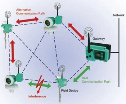
It turns out that you can get rid of the wires. Already in 2007, the WirelessHART Standard was published, the transmission medium is the unlicensed frequency of 2.4 GHz, which runs on many computer wireless devices, including wireless local area networks. Therefore, WirelessHART devices can be used without any restrictions. Figure 11 shows the WirelessHART wireless network.
Figure 11. Wireless WirelessHART
These technologies have replaced the old analog current loop. But she does not give up her position, it is widely used wherever possible.
Boris Aladyshkin
See also at bgv.electricianexp.com
:


