Categories: Featured Articles » Novice electricians
Number of views: 40673
Comments on the article: 0
Inductors and magnetic fields. Part 2. Electromagnetic induction and inductance
The first part of the article: Inductors and magnetic fields
The relationship of electric and magnetic fields
 Electrical and magnetic phenomena have been studied for a long time, but it never occurred to anyone to somehow relate these studies to each other. And only in 1820 it was discovered that a current conductor acts on the compass needle. This discovery belonged to Danish physicist Hans Christian Oersted. Subsequently, the unit of measurement of the magnetic field strength in the GHS system was named after him: the Russian designation E (Oersted), the English designation Oe. The magnetic field has such intensity in a vacuum during induction of 1 Gauss.
This discovery suggested that a magnetic field could be obtained from an electric current. But at the same time, thoughts arose about the inverse transformation, namely, how to get an electric current from a magnetic field. Indeed, many processes in nature are reversible: ice is obtained from water, which can again be melted into water.
After the discovery of Oersted, the study of this now obvious law of physics took as much as twenty-two years. The English scientist Michael Faraday was engaged in obtaining electricity from a magnetic field. Conductors and magnets of various shapes and sizes were made, and options for their mutual arrangement were sought. And only, apparently, by chance, the scientist discovered that in order to obtain EMF at the ends of the conductor, one more term is needed - the movement of the magnet, i.e. the magnetic field must be variable.
Now this does not surprise anyone. This is how all electric generators work - while it is being rotated with something, electricity is generated, a light bulb shines. Stopped, stopped turning, and the light went out.
Electromagnetic induction
Thus, the EMF at the ends of the conductor occurs only if it is moved in a certain way in a magnetic field. Or, more precisely, the magnetic field must necessarily change, be variable. This phenomenon is called electromagnetic induction, in Russian electromagnetic guidance: in this case they say that EMF is induced in the conductor. If a load is connected to such an EMF source, a current will flow in the circuit.
The magnitude of the induced EMF depends on several factors: the length of the conductor, the induction of the magnetic field B, and to a large extent on the speed of movement of the conductor in the magnetic field. The faster the generator rotor is rotated, the higher the voltage at its output.
Note: electromagnetic induction (the occurrence of EMF at the ends of a conductor in an alternating magnetic field) should not be confused with magnetic induction - a vector physical quantity characterizing the actual magnetic field.
Three ways to get EMF
Induction
This method has been considered. in the first part of the article. It is enough to move the conductor in the magnetic field of the permanent magnet, or vice versa to move (almost always by rotation) the magnet near the conductor. Both options will definitely allow you to get an alternating magnetic field. In this case, the method of obtaining EMF is called induction. It is induction that is used to obtain EMF in various generators. In the experiments of Faraday in 1831, the magnet progressively moved inside the wire coil.
Mutual induction
This name suggests that two conductors take part in this phenomenon. In one of them, a changing current flows, which creates an alternating magnetic field around it. If there is another conductor nearby, then at its ends there is a variable EMF.
This method of obtaining EMF is called mutual induction.It is on the principle of mutual induction that all transformers work, only their conductors are made in the form of coils, and cores made of ferromagnetic materials are used to enhance magnetic induction.
If the current in the first conductor stops (open circuit), or even becomes very strong, but constant (there are no changes), then at the ends of the second conductor no EMF can be obtained. That is why transformers operate only on alternating current: if a galvanic battery is connected to the primary winding, then there will definitely not be any voltage at the output of the secondary winding.
EMF in the secondary winding is induced only when the magnetic field changes. Moreover, the stronger the rate of change, namely the speed, and not the absolute value, the greater the induced EMF.

Self induction
If you remove the second conductor, then the magnetic field in the first conductor will permeate not only the surrounding space, but also the conductor itself. Thus, under the influence of its field in the conductor induced EMF, which is called the EMF of self-induction.
The phenomena of self-induction in 1833 were studied by the Russian scientist Lenz. Based on these experiments, an interesting pattern was found: the EMF of self-induction always counteracts, compensates for the external alternating magnetic field that causes this EMF. This dependence is called the Lenz rule (not to be confused with the Joule-Lenz law).
The minus sign in the formula just speaks of counteracting the EMF of self-induction by its causes. If the coil is connected to a direct current source, the current will increase quite slowly. This is very noticeable when the primary winding of the transformer is “dialed” with a dial ohmmeter: the speed of the arrow in the direction of zero scale division is noticeably lower than when testing resistors.
When the coil is disconnected from the current source, the self-induction EMF causes sparking of the relay contacts. In the case when the coil is controlled by a transistor, for example, a relay coil, a diode is placed parallel to it in the opposite direction with respect to the power source. This is done in order to protect the semiconductor elements from the influence of EMF self-induction, which can tens or even hundreds of times higher than the voltage of the power source.
For conducting experiments, Lenz constructed an interesting device. Two aluminum rings are fixed at the ends of the aluminum rocker arm. One ring is solid, and the other was cut. The rocker rotates freely on the needle.
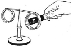
When a permanent magnet was introduced into a solid ring, it “escaped” from the magnet, and when the magnet was removed, it sought after it. The same actions with the cut ring did not cause any movements. This is due to the fact that in a continuous ring under the influence of an alternating magnetic field, a current arises that creates a magnetic field. But in the open ring there is no current, therefore, there is no magnetic field either.
An important detail of this experiment is that if a magnet is inserted into the ring and remains stationary, then no reaction of the aluminum ring to the presence of the magnet is observed. This once again confirms that the induction EMF occurs only in case of a change in the magnetic field, and the magnitude of the EMF depends on the rate of change. In this case, simply from the speed of movement of the magnet.
The same can be said about mutual induction and self-induction, only a change in the magnetic field strength, more precisely, its rate of change depends on the rate of change of current. To illustrate this phenomenon, we can give an example.
Let large currents pass through two sufficiently large identical coils: through the first coil 10A, and through the second as many as 1000, with the currents linearly increasing in both coils. Suppose that in one second the current in the first coil changed from 10 to 15A, and in the second from 1000 to 1001A, which caused the appearance of self-induction EMF in both coils.
But, despite such a huge value of the current in the second coil, the self-induction EMF will be greater in the first, since there the current change rate is 5A / s, and in the second it is only 1A / s. Indeed, the EMF of self-induction depends on the rate of increase of the current (read the magnetic field), and not on its absolute value.
Inductance
The magnetic properties of the coil with current depend on the number of turns, geometric dimensions. A significant increase in the magnetic field can be achieved by introducing a ferromagnetic core into the coil. The magnetic properties of the coil can be judged with sufficient accuracy by the magnitude of the EMF of induction, mutual induction, or self-induction. All these phenomena were considered above.
The characteristic of the coil, which talks about this, is called the coefficient of inductance (self-induction) or simply inductance. In formulas, the inductance is denoted by the letter L, and in the diagrams the same letter denotes the inductance coils.
The unit of inductance is Henry (GN). Inductance 1H has a coil in which, when the current changes by 1A per second, an EMF of 1V is generated. This value is quite large: network windings of sufficiently powerful transformers have an inductance of one or more GN.
Therefore, quite often they use values of a smaller order, namely, milli and micro-henry (mH and μH). Such coils are used in electronic circuits. One of the applications of coils is oscillatory circuits in radio devices.
Also, coils are used as chokes, the main purpose of which is to skip direct current without loss while weakening the alternating current (filters in power supplies) Generally, the higher the operating frequency, the less inductance coils are required.
Inductance
If you take a sufficiently powerful network transformer and measure with a multimeter resistance of the primary winding, it turns out that it is only a few ohms, and even close to zero. It turns out that the current through such a winding will be very large, and even tend to infinity. A short circuit seems to be inevitable! So why is he not?
One of the main properties of inductors is inductive resistance, which depends on the inductance and on the frequency of the alternating current that is connected to the coil.
It is easy to see that with an increase in the frequency and inductance, the inductive resistance increases, and in direct current it generally becomes equal to zero. Therefore, when measuring the resistance of coils with a multimeter, only the active resistance of the wire is measured.
The design of the inductors is very diverse and depends on the frequencies at which the coil operates. For example, for work in the decimeter range of radio waves, coils made by printed wiring are quite often used. In mass production, this method is very convenient.
The inductance of a coil depends on its geometrical dimensions, core, number of layers and shape. Currently, a sufficient number of standard inductors are produced, similar to conventional resistors with leads. Marking of such coils is carried out with colored rings. There are also surface mount coils used as chokes. The inductance of such coils is several milligenes.
See also at bgv.electricianexp.com
: