Categories: Featured Articles » Novice electricians
Number of views: 23752
Comments on the article: 2
Installation practice and modular grounding features
 Modular grounding - This is a project created specifically for the installation of grounding conductors at residential facilities, for example, such as suburban private houses, country houses, as well as for industrial and administrative facilities.
The practice of installing a modular grounding loop.
The modular earthing switch is a prefabricated structure consisting of steel pins specially treated with copper, each 1.5 meters long. These pins are combined into a single grounding ground loop of the object.
The length of the prefabricated grounding pin can reach a depth of about 30 - 40 meters. Earthing 1.5 meter pins have threads at the ends, through which the couplings between them, it becomes possible as the precast earthing pin moves in depth - to increase it with the next pin, etc.
Installation of a vertical grounding pin in depth is done as follows. The first pin is equipped with a steel tip from below, and an assembly sleeve with a nozzle for a vibratory hammer is screwed onto its upper part. To hit the nozzle use a hammer or punch, and to hold the pin in an upright position - use a special clip.
When the first pin enters the ground to a length of about 1.3 - 1.4 meters, the mounting sleeve with the nozzle for the vibratory hammer is removed, and instead the second pin is screwed through the connection sleeve. The special clamp for holding the pin in a vertical position moves upwards along the newly mounted structure, and its top is again equipped with an assembly sleeve and a hammer head and the process of driving the grounding pin continues.
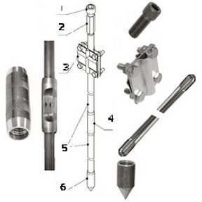
A diagram of the modular earthing pin is shown in the diagram below, where:
1. Nozzle under the hammer or vibratory hammer.
2. Mounting clutch.
3. Clamp to hold the grounding pin in an upright position.
4. Coupling.
5. Grounding rod.
6. Steel tip.

Modular pin earthing design
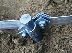
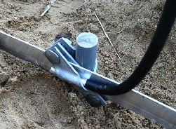
There are several such modular grounding conductors for the grounding circuit (according to the project), and then they are interconnected, using a copper strip or wire using clamps, into a single grounding circuit. When installing the clamps, these places are pre-treated with a conductive paste, and after the complete installation of the entire ground loop, it undergoes anti-corrosion paint.
Measurement of the resistance of the mounted vertical pin is possible at the installation stage of each newly screwed 1.5 meter pin, and the life of such a modular grounding loop is approximately 30 years.
Advantages and disadvantages of a modular grounding loop.
Advantages of modular grounding.
 • Ease of installation work on the modular pin ground loop.
• Participation in installation work of a minimum of workers (only 2 people).
• Due to the minimum area for grounding electrodes - there is the possibility of mounting this type ground loop near walls and even in the basements of houses.
• Installation of all elements of the modular pin earthing loop is carried out without welding.
• All elements of the modular design of grounding are manufactured industrially and therefore they are of high quality and immediately ready for installation.
• Steel grounding pins with a special copper coating are quite resistant to corrosion and easily clog into the ground to a great depth.
The disadvantages of modular pin grounding.
• The main disadvantage of modular grounding is its rather high cost.
Summarizing the material we presented, we can say that the industry now produces various sets of high-quality modular pin grounding, combining any elements necessary for high-quality and reliable installation.
We recommend reading: How to make grounding in a country house
See also at bgv.electricianexp.com
:
