Categories: Featured Articles » Novice electricians
Number of views: 208579
Comments on the article: 2
Transistor operation in key mode
 To simplify the story, you can imagine transistor in the form of a variable resistor. The conclusion of the base is just the very handle that you can twist. In this case, the resistance of the collector - emitter section changes. Of course, you don’t need to twist the base, it can come off. But to apply some voltage to it relative to the emitter, of course, is possible.
If the voltage is not applied at all, but simply take and close the conclusions of the base and emitter, even if not short, but through a resistor of several KOhms. It turns out that the base-emitter voltage (Ube) is zero. Consequently, there is no base current. The transistor is closed, the collector current is negligible, just the same initial current. About the same as a diode in the opposite direction! In this case, they say that the transistor is in the OFF position, which in ordinary language means it is closed or locked.
The opposite state is called SATURATION. This is when the transistor is fully open, so that there is nowhere to open further. With such a degree of opening, the resistance of the collector-emitter section is so small that it is simply impossible to turn on the transistor without load in the collector circuit, it will burn instantly. In this case, the residual voltage at the collector can be only 0.3 ... 0.5V.
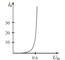
To bring the transistor to such a state, it is necessary to provide a sufficiently large base current by applying a large voltage Ube to it relative to the emitter, of the order of 0.6 ... 0.7V. Yes, for a base-emitter junction, such a voltage without a limiting resistor is very large. After all, the input characteristic of the transistor, shown in Figure 1, is very similar to the direct branch of the diode's characteristic.
Figure 1. Transistor input characteristic
These two states — saturation and cutoff — are used when the transistor is in key mode like a normal relay contact. The main point of this mode is that a small base current controls a large collector current, which is several tens of times greater than the base current. A large collector current is obtained due to an external energy source, but still the current gain, as they say, is obvious. A simple example: a small microcircuit turns on a large light bulb!
To determine the magnitude of such a gain of the transistor in the key mode, the "current gain in the large signal mode" is used. In the directories from is indicated by the Greek letter β "betta". For almost all modern transistors, when operating in key mode, this coefficient is no less than 10 ... 20 β is determined as the ratio of the maximum possible collector current to the minimum possible base current. The size is dimensionless, just "how many times."
β ≥ Ic / Ib
Even if the base current is more than required, there is no particular trouble: the transistor will still not be able to open more. That's why it is in saturation mode. In addition to conventional transistors, Darlington or composite transistors are used to operate in key mode. Their "super - betta" can reach 1000 or more times.
How to calculate the key stage operation mode
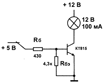
In order not to be completely unfounded, let us try to calculate the operation mode of the key cascade, the circuit of which is shown in Figure 2.
Figure 2
The task of this cascade is very simple: turn on and off the light bulb. Of course, the load can be anything - a relay coil, an electric motor, just a resistor, but you never know what. The light bulb was taken just to make the experiment clear, to simplify it. Our task is a little more complicated. It is required to calculate the value of the resistor Rb in the base circuit so that the bulb burns into full heat.
Such bulbs are used to illuminate the dashboard in domestic cars, so finding it is easy. The KT815 transistor with a collector current of 1.5A is quite suitable for such an experience.
The most interesting thing in this whole story is that stresses are not taken into account in the calculations, so long as the condition β ≥ Ic / Ib is met. Therefore, the bulb can be at an operating voltage of 200V, and the base circuit can be controlled from microchips with a supply voltage of 5V. If the transistor is designed to work with such a voltage on the collector, the light will flash without problems.
But in our example, no microcircuits are expected, the base circuit is controlled simply by a contact, which simply supplies 5V. Light bulb for voltage 12V, consumption current 100mA. It is assumed that our transistor has β exactly 10. The voltage drop at the base-emitter junction is Ube = 0.6V. See input characteristic in figure 1.
With such data, the current in the base should be Ib = Ik / β = 100/10 = 10 (mA).
The voltage at the base resistor Rb will be (minus the voltage at the base-emitter junction) 5V - Ube = 5V - 0.6V = 4.4V.
We recall Ohm's law: R = U / I = 4.4V / 0.01A = 440ohm. According to the SI system, we substitute the voltage in volts, the current in amperes, the result is in Ohms. From the standard series, we select a resistor with a resistance of 430 Ohms. On this calculation can be considered complete.
But, who carefully looks at the circuit, may ask: “Why was nothing said about the resistor between the base and the emitter Rbe? They just forgot about him, or is he really needed? ”
The purpose of this resistor is to reliably close the transistor at the moment when the button is open. The fact is that if the base “hangs in the air”, the effect of all kinds of interference on it is simply guaranteed, especially if the wire to the button is long enough. What is not the antenna? Almost like a detector receiver.
To reliably close the transistor, to enter it in the cut-off mode, it is necessary that the potentials of the emitter and the base are equal. It would be easiest to use a switching contact in our “training scheme”. It is necessary to turn on the light switch contact to + 5V, and when it was required to turn off - just closed the input of the entire cascade to ground.
But it is not always and not everywhere that luxury can be allowed such as extra contact. Therefore, it is easier to align the potentials of the base and emitter with the resistor Rbe. The value of this resistor does not need to be calculated. Usually it is taken equal to ten RB. According to practical data, its value should be 5 ... 10K.
The considered circuit is a type of circuit with a common emitter. Two features can be noted here. Firstly, this is using 5V as the control voltage. It is this voltage that is used when the key stage is connected to digital circuits or, which is now more likely to microcontrollers.
Secondly, the collector signal is inverted with respect to the base signal. If there is voltage at the base, the contact is closed at + 5V, then on the collector it drops to almost zero. Well, not to zero, of course, but to the voltage indicated in the directory. At the same time, the bulb is not visually inverted - there is a signal at the base, there is light.
Inverting the input signal occurs not only in the key mode of the transistor, but also in gain mode. But this will be discussed in the next part of the article.
Boris Aladyshkin
P.S. Before installing in the circuit, it is very often necessary to check the transistors for operability. See how to do it right here - Simple transistor testing in practice.
See also at bgv.electricianexp.com
:


