Categories: Featured Articles » Novice electricians
Number of views: 7830
Comments on the article: 1
Grounding wire - cross-section, marking, color, connection, requirements for grounding conductors
Most electrical installations are always earthed using a special ground wire. The ground wire is designed to connect the conductive elements of the installation to the ground, which initially has zero potential, and thereby create a safe zero potential on the grounding element.
The main purpose of the ground wire is to protect a person from electric shock if the phase voltage supplying the unit for some reason gets on its case.

An example is a washing machine, in the wiring of which the insulation is damaged over time and the bare phase wire at some point touches its metal case of a household appliance.
In this case, the person is at risk, because if he touches the car’s body, he will get an electric shock, since the current will flow through his body in the direction of the earth, but the person is practically on the floor, which is not always reliably isolated from grounded conductive objects, the same heating radiators or fittings.
It should be understood that even a small alternating current, of the order of 60 mA, can prove fatal for a person, especially if this current passes through the heart.
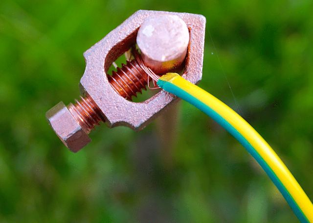
To completely eliminate the risk of electrical injury and death, domestic and industrial electrical installations are always equipped with a grounding wire.
This wire electrically connects all the conductive elements of the installation, which in normal mode should not be energized, with an earth circuit with zero potential. In this case, during phase breakdown to the housing (or to another conductive part of the device protected by grounding), the current will immediately flow into the ground along the path of least resistance, that is, through the grounding wire. And if there is a chain residual current device (RCD), then it will certainly work.
First of all, in most installations, the purpose of the ground wire is to protect people, but in some cases, grounding is necessary to ensure the normal operation of the appliance. Thus, the ground wires are divided into protective and working.
In any case, the ground conductor, whether it is working or protective, must be correctly mounted and must comply with certain requirements. These requirements are determined by the operating conditions of the plants and their operating modes. In the end, there are specific criteria that we consider below.
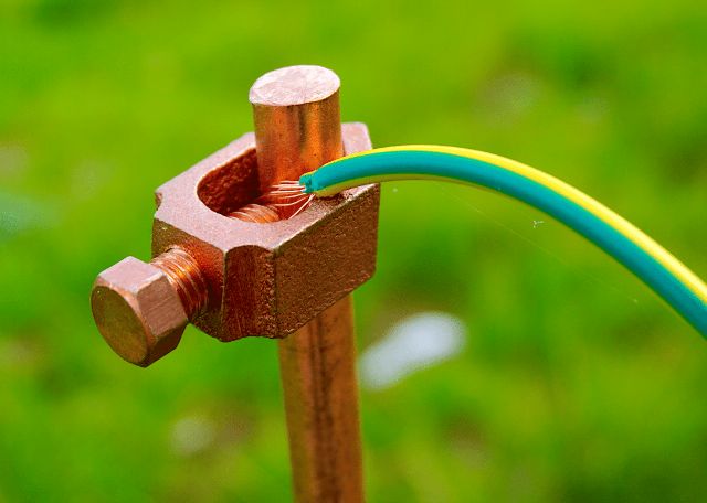
Ground wire requirements
If the protected equipment, and first of all, its case, is installed permanently and does not imply frequent movement from place to place, then a single-wire single-wire wire is used as grounding wire.
If, for example, a shield door is grounded, which moves from time to time, then a flexible multicore wire is needed.
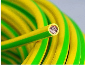
When the protective conductor is laid along the equipment case or laid openly, it must always be insulated. With hidden wiring, a bare conductor is allowed.
When a single-phase wiring is still being mounted, it is advisable to make it with a three-wire cable, one of the conductors in which will be protective, grounded, if we are talking about a three-phase system, then use a five-wire cable. If the wiring is already laid, and there is no grounding, the grounding conductor is laid separately.
Role of resistance
It is very important that the electrical resistance of the ground wire is small.For this reason, conductors with copper conductors are most often used as grounding wires, since copper has a higher conductivity than aluminum or steel.
The ohmic resistance of the ground loop together with the ground conductor connected to it is extremely important. Here, factors such as: the cross-section of the wire, the transition resistance at the points of contact of the conductor with the equipment and with the ground loop (bolts, welding) and the ground loop - with the ground influence it.
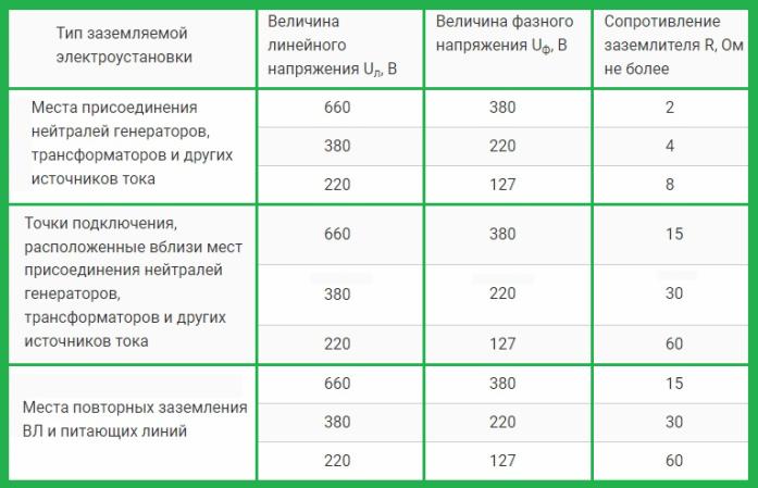
Depending on the type of electrical installation, on the values of phase and linear voltages, according to PUE 1.7.101 - 1.7.103, the requirements for resistance are as follows:
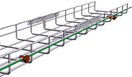
By the way, according to PUE 1.7.121, it is possible to use not necessarily separately laid copper wires as grounding conductors, it is also allowed to use a conductive armored cable sheath, (whose direct purpose is to protect the cable from mechanical damage) as well as trays, boxes, rails, beams, and structural parts of structures, with the exception of (according to PUE 1.7.123) metal parts of water supply pipes and gas pipelines, as well as fittings that form the basis of reinforced concrete structures.
Color and letter marking of the ground wire
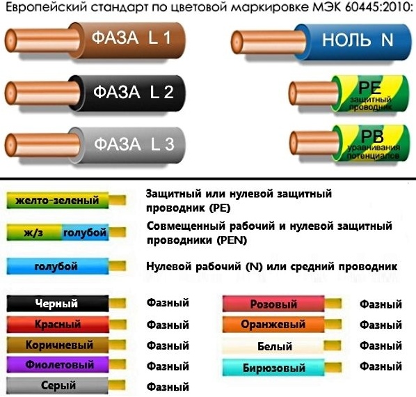
So that the ground wire can be easily recognized and distinguished from other wires, it corresponds to an individual color and letter marking, this provision is regulated by PUE 1.1.29. The letters PE, applied to the terminals, cable ends and circuits, indicate earth.
The characteristic color of the ground wire is yellow-green, yellow and green strips are usually applied along the entire length of the insulation of the wire, or in a different configuration, but so that these two colors are easily recognizable.

In some networks, the protective earth conductor is aligned with the neutral conductor. But the zero conductor, according to PUE 1.1.29, is marked in blue and has the designation N. However, in cases where these conductors are combined, the color marking will combine blue and yellow-green insulation.
The letter designation will be replaced by PEN. This marking does not apply directly to the power bus, since red, yellow and green indicate phases in this case, and the neutral conductor may be colorless. The PE bus is painted black as part of the cable.
Ground wire cross section
With the active resistance of the ground wire, the effectiveness and speed of the operation of an RCD, and therefore the reliability of protecting a person from electric shock, are directly related. Therefore, the cross section of the ground wire must comply with the operating parameters of the line to which this ground is related.
In practice, the ground conductor is not designed to withstand such a significant load as the phase conductors and the neutral conductor should carry. For this reason, the cross-section of the ground conductor is taken to be slightly smaller.
In accordance with PUE 1.7.126, the cross-sectional area of the grounding conductor PE is taken based on the area of the phase conductors of the particular line under consideration. So, if the cross section of the phase conductor is less than 16 square mm, then the cross section of the ground conductor should be similar.
If the phase has a cross section of 16 to 35 square mm, then the cross section of the ground conductor cannot be less than 16 square mm. If the phase conductors differ in cross section exceeding 35 square mm, then the cross section of the ground conductor cannot be less than half the cross section of such a phase conductor. In addition, it is advisable to use the formula to more accurately determine the cross section of the grounding conductor in order to save materials:

Here, the value of the short-circuit current I, the response time of the protective device t, and also the coefficient C characterizing the material of the conductors and its insulation are taken into account.
Ground wire connection
Before connecting the ground wire, they find and designate the conclusions of all cable cores from two ends.Cores are easy to find by color coding. Phase conductors have a variety of color coding.
Blue or blue is the neutral conductor. The ground conductor is always highlighted in yellow-green or bright green. If there is no confidence in observing the standard and the installation procedure for the markings, the wires should be ringed first.
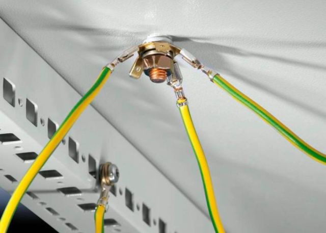
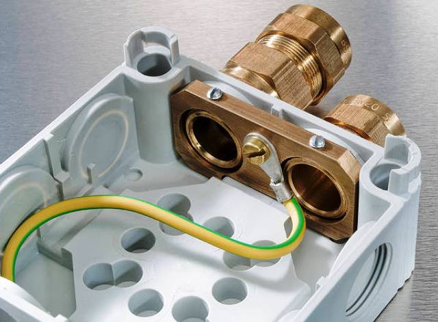
When all conductors are properly identified, proceed with connecting the ground conductor. It is mandatory to use crimping, crimping, soldering, ferrules or tightening with a screw and nut. Twisting is not allowed.
When connecting conductors of different metals (for example, copper and aluminum) - use a crimp sleeve. After connecting the conductors to each other, the ground wire is connected on one side to the ground loop, and on the other - to the enclosure of the protected equipment.
See also at bgv.electricianexp.com
:
