Categories: Featured Articles » Novice electricians
Number of views: 31654
Comments on the article: 0
What is a solid state relay and how to use it correctly
In all electrical circuits have to turn on and off the instruments and devices. To do this, use switching devices, it can be either a simple switch or switch, or relays, contactors, etc. Today we will consider one of such devices - a solid state relay, talk about what it is like to select and connect to a load control circuit.

What it is
Solid state relay Is a device built on semiconductor elements and power switches, such as triacs, bipolar or MOS transistors. In English sources, solid state relays are called SSR from Solid State Relay (which in the literal translation is equivalent to the Russian name).
Like at electromagnetic relays and other switching devices, they are designed to control a weak signal with a load with a higher voltage or current.
Differences from electromagnetic relays
Conventional relays, like all electromagnetic switching devices, work as follows - there is a coil to which current is supplied from the control system or the push-button station. As a result of the current flowing through the coil, a magnetic field appears, which attracts the armature with the contact group. After that, the contacts close and current flows into the load through them.
Solid-state ones have no control coil and no moving contact group. What inside the solid state relay you can see below. In it, as mentioned above, instead of power contacts, semiconductor switches are used: transistors, triacs, thyristors and others, depending on the application (the right side of the photo).

This is the main difference between a semiconductor relay and an electromagnetic one. In this regard, the solid-state has a significantly longer service life, since there is no mechanical wear of the contact group, it is also worth noting that the speed of semiconductor relays is higher than that of electromagnetic ones.
In addition to the absence of mechanical wear, there are no sparks or arcs during switching, as well as sounds from impacts of contacts during switching. By the way, if there are no sparks and arc discharges during switching, solid-state relays can work in explosive rooms.
Comparison
The advantages of solid-state relays in comparison with electromagnetic relays are as follows:
1. Noiselessness.
2. There is evidence that their MTBF of the order of 10 billion switches, which is 1000 or more times the resource of electromagnetic relays.
3. If for electromagnetic relays, surge voltage is practically not terriblethen the electronic circuit semiconductor relay in most cases failsif no circuitry decisions were made to limit these pulses. Therefore, comparing these devices by the number of switching is not always correct.
4. Performance a semiconductor relay is fractions and units of milliseconds, while an electromagnetic relay has 50 ms to 1 s.
5. Energy consumption is 95% lower than the coil consumption of electromagnetic analogues.
However, these advantages are covered by a number of disadvantages:
-
Semiconductor relays heat up during operation. Power equal to the product of the voltage drop across the power switch (of the order of 2 volts) and the current flowing through it is released into heat;
-
When overloading and short circuits there is a high probability of failure of the power switch, the overload capacity is usually 10In for 10 ms - one period in the network with a frequency of 50 Hz (may vary depending on the components used);
-
The circuit breaker, most likely, will not have time to trip before the relay fails during a short circuit;
-
In case of surge voltages (power surges) - the service life of a solid-state relay can end instantly.
-
Solid state relays have a leakage current (up to 7-10 mA) in connection with this, if they are in the control circuit, for example, LED lamps - the latter will flash similarly to the situation with the backlit switch. Accordingly, there will be voltage on the phase wire even when the relay is disconnected!
The following table shows the general characteristics of solid-state relays of the TSR (three-phase) and SSR (single-phase) series from the manufacturer "FOTEK" (by the way, some of the most common). In principle, other manufacturers will have similar or similar product specifications.
Kinds
Solid state relays can be classified:
-
By type of current (constant or alternating);
-
By current strength (low-power, power);
-
According to the installation method;
-
By voltage;
-
By the number of phases;
-
By type of control signal (direct or alternating current, analog input for controlling a variable resistor, in a 4-20 mA circuit, etc.).
-
By type of switching - switching when the voltage passes through zero (in AC circuits), or switching by a control signal (for adjusting power, for example).


So, by the number of phases there are single and three phase relays. But the types of control signals are much more. Depending on the internal device, solid-state relays can be controlled by either a constant voltage or an alternating voltage.
The most common solid state relays that are controlled by constant voltage in the range from 3 to 32 volts. In this case, the magnitude of the controlled voltage should be in this range, and not be equal to any specific value from it, which is very convenient when integrated into systems with different voltages.
There are also semiconductor relays, for the control of which an analog signal is used:
-
4-20 mA;
-
0-10 volts of direct current;
-
Variable resistor 470-560 kOhm.
In this case, such relays can be used to regulate the power on the connected device, according to the principle of phase control. The same adjustment principle is used in household dimmers for lighting.
In the table below you see the types of control signals of solid-state relays with a phase control method from IMPULS.
Pay attention to the last letters of the marking (LA, VD, VA), for most manufacturers they are the same, and they say, just about the type of signal.

As already mentioned, in a phase-controlled relay, depending on the magnitude of the control signal, the output voltage changes, which is shown in the graph below.


Such a relay can be recognized by the conditional image near the input terminals, for example, the photo below shows that a 470-560 kOhm variable resistor is connected to the input.

There are also solid state relays with a control signal from an AC 220V network, as shown below. They are suitable for use as a replacement for low power contactors or electromagnetic relays.
Marking and type of control
To determine the "phase" of the relay, use the symbols at the beginning of the marking:
-
SSR - single phase;
-
TTR - three phase.
Which is equivalent to single-pole and three-pole switching devices.
The current strength is also encrypted, for example, FOTEK indicates it in the form: Pxx
Where "xx" is the current in amperes, for example, P03 - 3 amperes, and P10 - 10 amperes.

If the marking contains the letter H, then this relay is intended for switching overvoltage.
In the marking, data on the type of control are indicated in the last characters, it may differ from one manufacturer to another, but often it has this form and meaning (data are collected from different manufacturers):
-
VA - variable resistor 470-560kOhm / 2W (phase control);
-
LA - 4-20mA analog signal (phase control);
-
VD - analog signal 0-10V DC (phase control);
-
ZD - control 10-30V DC (switching when going through zero);
-
ZD3 - control 3-32V DC (switching when going through zero);
-
ZA2 - control 70-280V AC (switching when going through zero);
-
DD3 - control of a 3-32V DC signal by a direct current circuit (DC voltage switching);
-
DA - DC signal control, AC circuit switching.
-
AA - AC signal control (220V), AC circuit switching.
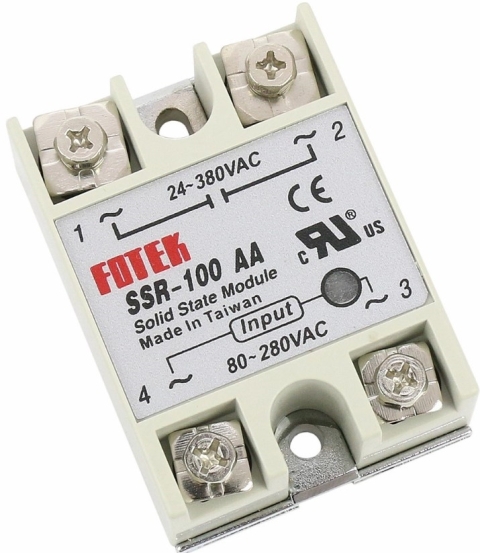
Let's check it in practice, let's say you came across such a product as in the figure below, and want to know what it is.
If you carefully study the inscriptions near the terminals for connecting wires, it will already become clear that this is a relay for controlling AC circuits from 90 to 480 volts, while control also occurs with alternating current with a voltage from 80 to 250 volts.
If only the marking is visible, then: “SSR” is single-phase; "-10" - rated current of 10 amperes; “AA” - AC control, AC switching; “H” - for switching high voltage in the power circuit - up to 480V (if there were no H, it would be up to 380-400V).
And for consolidation and a better understanding, study the following table with the markings and characteristics of solid state relays.

Device
The internal circuit of a solid-state relay depends on what current it is designed for (direct or alternating) and the type of signal to control it. Let's consider some of them.
Let's start with the relay, which is controlled by direct current and commutes when going through zero. They are sometimes called "Z-Type Solid State Relays."

Here, pins 3-4 is the control signal input, which uses optocoupler control, which is used for galvanic isolation of input and output circuits.
The block controlling the transition through 0, or as it is called Zero Cross Circuit - monitors the phase of the voltage in the mains and when it passes through zero it makes a circuit switching (on or off). This method is also called Zero Voltage Switch, it allows to reduce inrush currents when turned on (since the voltage at this moment is equal to zero) and surges of EMF self-induction when the load is disconnected.
Suitable for controlling resistive, capacitive and inductive loads. Not suitable for controlling a high inductive load (with cos cos <0.5), such as transformers idling. Also, this control method does not interfere with the mains during switching. Below you see diagrams of control signals, mains voltage and load current with this control method.

Schematically, this is implemented as follows:

Here, the voltage from the network is supplied to a block with a triac and a block that tracks the transition through zero. Elements Q1, R3, R4, R5, C4 at high voltage block the opening of thyristor T2, which controls the power triac T1. Then switching is possible only with a voltage close to zero. The input circuit is made on U1 - a transistor optocoupler, which supplies a signal to the control electrode of the driver of the triac T2, through Q2.
Instantaneous relays are arranged somewhat differently than switching relays when crossing zero. They lack the ZCC cascade.
When controlling AC, the circuit differs only in the presence of at the input of the rectifier (diode bridge).

And when switching DC circuits, the triac is replaced by a transistor.

There are also universal relays for direct and alternating current, where an assembly of transistors is used. In general, there are many circuits of output stages of solid state relays, the following are examples of circuitry of different models from a manufacturer such as International Rectifier.

In a relay with a phase control method, the situation is somewhat different. Like a dimmer, it can adjust the load power (output voltage), for this an analog signal is applied to the input - voltage, current, or an alternating resistance is connected. As a power element, a thyristor is used here.But keep in mind that due to this method of adjustment, interference occurs in the network, to suppress which network filters with common-mode chokes are used, but this is a completely different topic.

You can see the differences in switching when going through zero from phase switching in the figure below.

Connection diagrams and usage features
In fact, the connection diagram of solid-state relays is almost no different from conventional ones. How to connect? Let's get it right.

If you need to replace a conventional 220V relay with 220V AC control, use the following diagram, for example LDG LDSSR-10AA-H. The diagram for example shows the connection through a conventional switch or toggle switch. Instead, an enable signal can be supplied from a thermostat, controller, and other devices.
If you need to control a 220V circuit using a low-voltage signal, you can use the FOTEK HPR-80AA.

In this circuit, a 12VDC power supply is used as a low-voltage direct current source, which are widely used as power supplies for LED strips. By the way, you can even control such a solid-state relay by applying voltage from the charger of the mobile phone to the input, because its output is 5V, which is more than the minimum signal of 3V.
Note also that the control voltage must be completely disconnected, since each relay has certain parameters at which it operates, for example, the above voltage is about 1 volt, and it can trip not at 3 rated volts, but already at 2.5 (The data are averaged, for example, and may vary depending not only on a particular product, but also on environmental conditions and installation.)
But recall that there is also a relay with a phase control method. The connection diagrams of such relays are illustrated below (illustration from the instructions for them).

The question is why such relays are needed and where are they used? The search for the answer to this question was short-lived, as soon as I entered the beginning of the query and immediately issued options for using as a power key for controlling heating elements from thermostats with an output of 4-20 mA or 0-10V.

By the way, for industrial applications there are also domestic developments, for example, ARIES TPM132 and other models that can work with 4-20mA and 0-10V output signals.
However, using a solid state relay to control a heavy load is not possible without cooling. For this, passive (simple radiator) or active cooling (radiator + cooler) is used.

Recommendations for choosing coolers are given in the technical documentation for a specific solid-state relay, so you can not give universal advice.
Conclusion
Solid state relays can be used as electromechanical relays in some cases. The most popular options in everyday life are replacing the contactor in an electric boiler, due to its loud popping when turned on, respectively, and inclusion TENOV will become silent.

As well as the implementation of various powerful power controllers for the same heating elements and other things, for which a solid-state relay with an analog signal input from a variable resistance (type VA) is used.
Radio amateurs can assemble the simplest solid-state relay, based on an optical driver for triacs with ZCC type MOC3041 and the like.

I believe that these are worthy products for use in various automation tools, in addition, they do not require maintenance (except for cleaning radiators from dust), and the service life can be said to be unlimited. They will last several times longer than contactors, provided there are no overloads, overheating, short-circuit and surge surges!
See also at bgv.electricianexp.com
: