Categories: Featured Articles » Novice electricians
Number of views: 56510
Comments on the article: 3
What is voltage, how to lower and increase voltage
Voltage and amperage are the two main quantities in electricity. In addition to them, a number of other quantities are also distinguished: charge, magnetic field strength, electric field strength, magnetic induction and others. A practicing electrician or electronics engineer in everyday work most often has to operate with voltage and current - Volts and Amps. In this article, we will talk specifically about tension, about what it is and how to work with it.
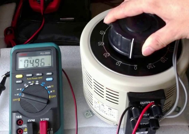
Determination of physical quantity
Voltage is the potential difference between two points, characterizes the work performed by the electric field to transfer charge from the first point to the second. Measured voltage in Volts. This means that voltage can be present only between two points in space. Therefore, it is impossible to measure the voltage at one point.
The potential is indicated by the letter "F", and the voltage by the letter "U". If expressed in terms of the potential difference, the voltage is:
U = F1-F2
If expressed through work, then:
U = A / q,
where A is work, q is charge.
Voltage measurement
Voltage is measured with a voltmeter. The voltmeter probes connect voltage to two points between which we are interested, or to the terminals of the part, the voltage drop at which we want to measure. Moreover, any connection to the circuit can affect its operation. This means that when a load is added parallel to an element, the current in the circuit changes and the voltage on the element changes according to Ohm's law.
Conclusion:
The voltmeter should have the highest input resistance so that when it is connected, the total resistance in the measured section remains almost unchanged. The resistance of the voltmeter should tend to infinity, and the greater it is, the greater the reliability of the readings.
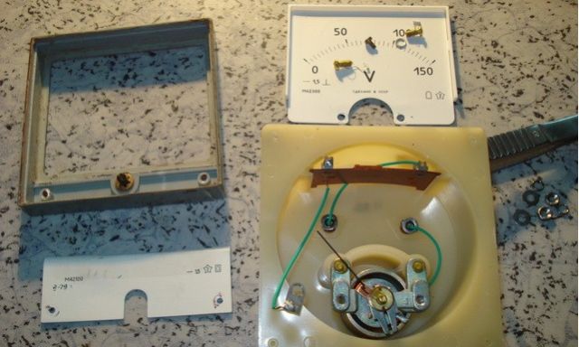
The measurement accuracy (accuracy class) is influenced by a number of parameters. For dial gauges, this includes the accuracy of the graduation of the measuring scale, design features of the arrow suspension, the quality and integrity of the electromagnetic coil, the condition of the return springs, the accuracy of the shunt selection, etc.
For digital devices - mainly the accuracy of the selection of resistors in the measuring voltage divider, the resolution of the ADC (the more the more accurate), the quality of the measuring probes.
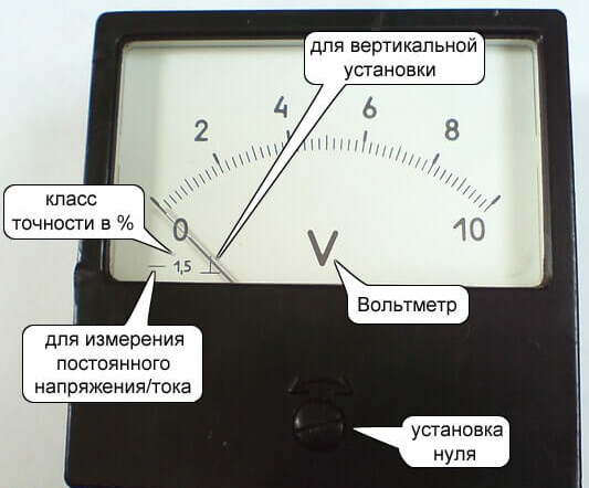
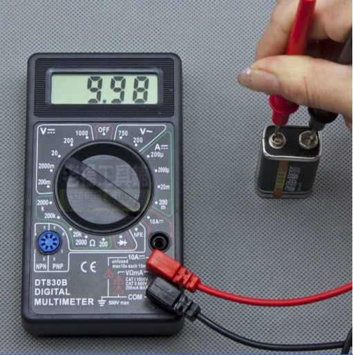
To measure DC voltage with a digital instrument (e.g. multimeter), as a rule, the correct connection of the probes to the measured circuit does not matter. If you connect a positive probe to a point with a more negative potential than the point to which a negative probe is connected, then a “-” sign will appear in front of the measurement result.
But if you measure with a pointer device, you need to be careful. If the probes are not connected correctly, the arrow will begin to deviate towards zero, it will rest against the limiter. When measuring voltages close to the measurement limit or more, it can jam or bend, after which it is not necessary to speak about the accuracy and further operation of this device.
For most measurements in everyday life and in electronics at an amateur level, a voltmeter built into multimeters such as DT-830 and the like is enough.
The larger the measured values, the lower the accuracy requirements, because if you measure volts and you have an error of 0.1V, this will significantly distort the picture, and if you measure hundreds or thousands of volts, then an error of 5 volts will not play a significant role.
What to do if the voltage is not suitable for supplying the load
To power each specific device or device, you need to apply a voltage of a certain value, but it happens that the power source you have is not suitable and produces a low or too high voltage.This problem is solved in various ways, depending on the required power, voltage and current strength.
How to lower the voltage resistance?
Resistance limits the current and when it flows, the voltage drops to the resistance (current-limiting resistor). This method allows you to lower the voltage to power low-power devices with currents of tens, maximum hundreds of milliamps.
An example of such a power supply is the inclusion of an LED in a DC network 12 (for example, an on-board vehicle network of up to 14.7 Volts). Then, if the LED is designed to be powered from 3.3 V, with a current of 20 mA, you need a resistor R:
R = (14.7-3.3) /0.02) = 570 Ohm
But resistors differ in maximum power dissipation:
P = (14.7-3.3) * 0.02 = 0.228 W
The closest one at face value is a 0.25 W resistor.
It is the power dissipation that imposes a restriction on this type of power supply, usually power resistors does not exceed 5-10 watts. It turns out that if you need to pay off a large voltage or power the load in this way, you will have to put several resistors as the power of one is not enough and it can be distributed among several.
A method of reducing voltage with a resistor works in both DC and AC circuits.
The disadvantage is that the output voltage is not stabilized in any way and with increasing and decreasing current it changes in proportion to the value of the resistor.
How to reduce alternating voltage with a choke or capacitor?
If we are only talking about alternating current, then we can use reactance. Reactive resistance is only in AC circuits, this is due to the features of energy storage in capacitors and inductors and switching laws.
Inductor choke and capacitor can be used as ballast.
The reactance of the inductor (and any inductive element) depends on the frequency of the alternating current (for a household electrical network of 50 Hz) and inductance, it is calculated by the formula:

where ω is the angular frequency in rad / s, L-inductance, 2pi is necessary for converting the angular frequency to normal, f is the voltage frequency in Hz.
The reactance of a capacitor depends on its capacitance (the lower C, the greater the resistance) and the frequency of the current in the circuit (the higher the frequency, the lower the resistance). It can be calculated as follows:

An example of the use of inductive resistance is the supply of fluorescent lighting lamps, DRL lamps and DNaT. The inductor limits the current through the lamp, in LL and DNT lamps it is used in conjunction with a starter or a pulsed ignition device (start relay) to form a high voltage surge that turns on the lamp. This is due to the nature and principle of operation of such lamps.
A capacitor is used to power low-power devices, it is installed in series with the power circuit. Such a power supply is called a "transformerless power supply with a ballast (blanking) capacitor."
Very often they are found as a current limiter for the charge of batteries (for example, lead) in portable flashlights and low-power radios. The disadvantages of such a scheme are obvious - there is no control of the battery charge level, their boiling off, undercharging, voltage instability.
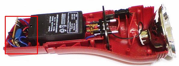
How to lower and stabilize DC voltage
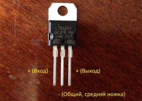
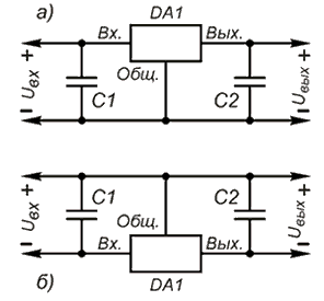
To achieve a stable output voltage, parametric and linear stabilizers can be used. Often they are made on domestic microcircuit type KREN or foreign type L78xx, L79xx.
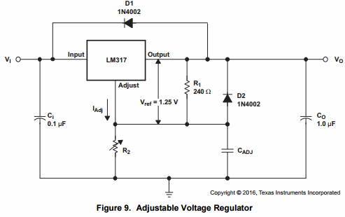
The LM317 linear converter allows you to stabilize any voltage value, it is adjustable up to 37V, you can make the simplest regulated power supply based on it.
If you need to slightly reduce the voltage and stabilize it, the described ICs will not work. For them to work, there must be a difference of the order of 2V or more. For this, LDO (low dropout) stabilizers are created.Their difference lies in the fact that in order to stabilize the output voltage, it is necessary that the input voltage exceed it by a value of 1V. An example of such a stabilizer is AMS1117, available in versions from 1.2 to 5V, most often they use versions of 5 and 3.3V, for example in Arduino boards and much more.
The design of all the above-described linear step-down stabilizers of a sequential type has a significant drawback - low efficiency. The greater the difference between the input and output voltage, the lower it is. He simply “burns” the excess voltage, translating it into heat, and the energy loss is equal to:
Loss = (Uin-Uout) * I
AMTECH company produces PWM analogs of L78xx converters, they operate on the principle of pulse-width modulation and their efficiency is always more than 90%.
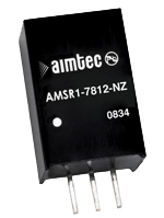
They simply turn on and off the voltage with a frequency of up to 300 kHz (ripple is minimal). And the current voltage is stabilized at the right level. And the switching circuit is similar to linear analogs.
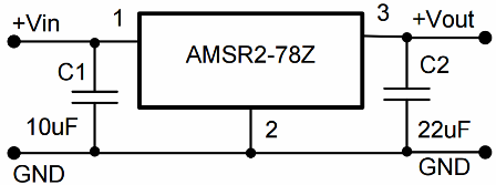
How to increase the constant voltage?
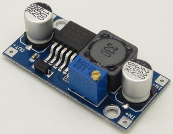
To increase the voltage produce pulse voltage converters. They can be included in the boost (boost), and buck (buck), and buck-boost (buck-boost) scheme. Let's look at a few representatives:
1. Board based on the XL6009 chip
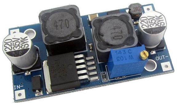
2. The board based on LM2577, works to increase and decrease the output voltage.
3. The converter board on the FP6291 is suitable for assembling a 5 V power supply, for example a powerbank. By adjusting the values of the resistors, it can be tuned to other voltages, like any other similar converter - you need to adjust the feedback circuits.
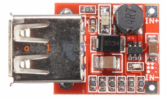
4. Board based on MT3608
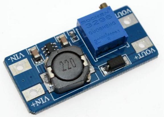
Everything is signed on the board here - the platform for soldering the input - IN and output - OUT voltages. The boards can have an adjustment of the output voltage, and in some cases, current limits, which makes it possible to make a simple and effective laboratory power supply. Most converters, both linear and pulse, are short-circuit proof.
How to increase alternating voltage?
To adjust the AC voltage, two main methods are used:
1. Auto transformer;
2. The transformer.
Auto transformer - This is a single winding inductor. The winding has a tap from a certain number of turns, so connecting between one of the ends of the winding and the tap, at the ends of the winding you get an increased voltage as many times as the total number of turns and the number of turns to the tap are related.
Industry produces LATRs - laboratory autotransformers, special electromechanical devices for voltage regulation. They found very wide application in the development of electronic devices and the repair of power supplies. Adjustment is achieved through a sliding brush contact to which the powered device is connected.
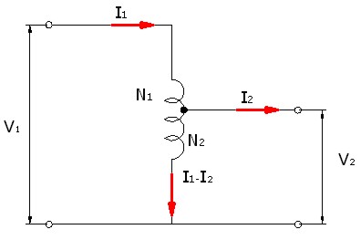
The disadvantage of such devices is the lack of galvanic isolation. This means that high voltage can easily turn out at the output terminals, hence the danger of electric shock.

Transformer - This is a classic way to change the magnitude of the voltage. There is galvanic isolation from the network, which increases the safety of such installations. The magnitude of the voltage on the secondary winding depends on the voltage on the primary winding and the transformation ratio.
Uvt = Uperv * Ktr
Ktr = N1 / N2
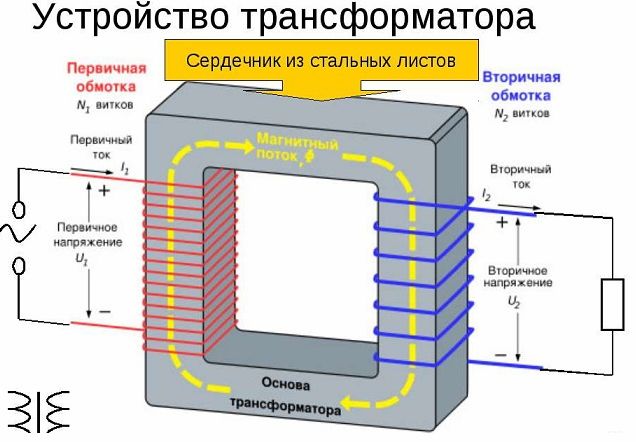
A separate view is pulse transformers. They operate at high frequencies of tens and hundreds of kHz. They are used in the vast majority of switching power supplies, for example:
-
Charger of your smartphone;
-
Laptop power supply;
-
Computer power supply.
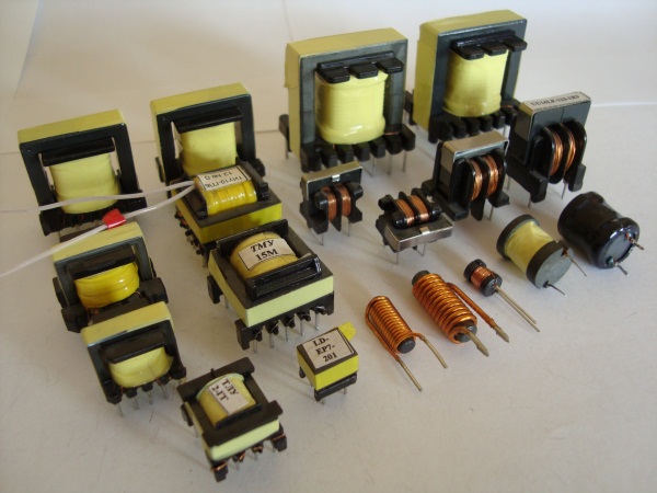
Due to the work at high frequency, the overall dimensions are reduced, they are several times less than that of mains (50/60 Hz) transformers, the number of turns on the windings and, as a result, the price.The transition to switching power supplies made it possible to reduce the dimensions and weight of all modern electronics and reduce its consumption by increasing efficiency (in pulse circuits, 70-98%).
Electronic transformers are often found in stores. A network voltage of 220 V is supplied to their input, and an output of 12 V, for example, is a high-frequency alternating current. diode bridge from high speed diodes.
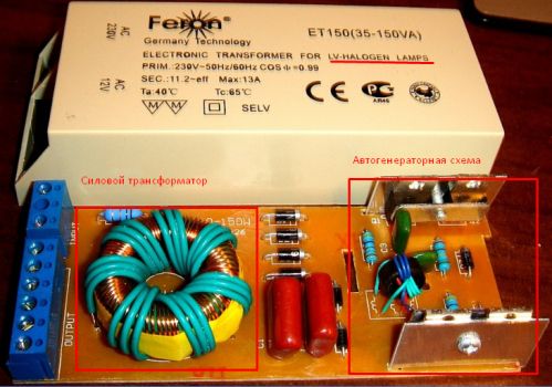
Inside is a pulse transformer, transistor switches, driver, or self-oscillating circuit, as shown below.
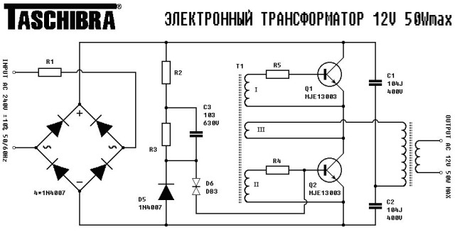
Advantages - simplicity of the circuit, galvanic isolation and small size.
Disadvantages - most of the models that are on sale have current feedback, which means that without a load with a minimum power (indicated in the specifications of a particular device) it simply will not turn on. Individual instances are already equipped with voltage operating systems and idle without any problems.
They are most often used to power 12V halogen lamps, for example spotlights of a suspended ceiling.
Conclusion
We looked at basic information about voltage, its measurement, and adjustment. A modern element base and an assortment of ready-made units and converters allows you to implement any power supply with the necessary output characteristics. You can write a separate article in more detail about each of the methods. Within this framework, I tried to fit the basic information necessary for the quick selection of a solution that is convenient for you.
See also at bgv.electricianexp.com
:
