Categories: Featured Articles » Novice electricians
Number of views: 8762
Comments on the article: 0
The main types of transformer designs
Among the diverse transformer devices, transformers are most often found:
-
power;
-
measuring;
-
special.
Power transformers
The term “power” defines the purpose associated with the conversion of high power. This is due to the fact that most household and industrial consumers of electric networks need power supply voltage of 380/220 volts. However, delivering it over long distances is associated with huge energy losses, which are reduced through the use of high-voltage lines.
High voltage overhead power lines are connected into a single network of the substation with power transformers of the corresponding class.
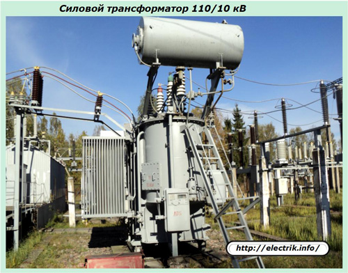
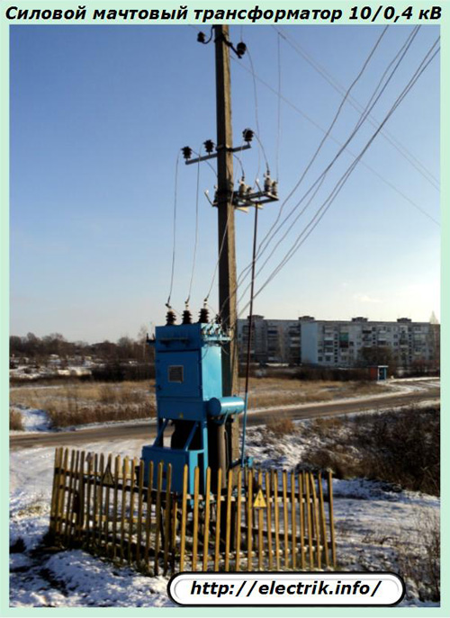
And on other lines, a voltage of 6 or 10 kV is supplied to power transformers that provide power to 380/220 volts residential complexes and manufacturing enterprises.
Instrument Transformers
In this class, there are two types of devices that provide for the measurement of network transformation parameters:
1. current;
2. voltage.
Measuring transformers are created with a high class of accuracy. During operation, their metrological characteristics are periodically checked for correct measurement of both the values and the angles of deviation of the current and voltage vectors.
Current transformers
Current transformer - a transformer whose primary winding is connected to a current source, and the secondary winding is closed to measuring or protective devices having low internal resistances.
Measuring current transformer - a transformer designed to convert current to a value convenient for measurement. The primary winding of the current transformer is connected in series to the circuit with the measured alternating current, and the measuring instruments are switched on to the secondary.
The main feature of their device is that they are constantly operated in the previously described (in the article about how the transformer is arranged and works) short circuit mode. Their secondary winding is completely shorted to a small resistance, and the rest of the design is adapted for such work.
To eliminate the emergency mode, the input power is limited by a special device of the primary winding: it creates only one turn, which cannot create a large voltage drop across the winding through it and, accordingly, transmit high power to the magnetic circuit.
This coil cuts directly into the power circuit, ensuring its serial connection. For individual structures, a through hole in the core is simply created through which a wire with primary current is passed.
The load on the secondary circuits of a live current transformer must not be broken. For this reason, all wires and connection terminals are manufactured with increased mechanical strength. Otherwise, at the broken ends, a high voltage voltage immediately arises, which can damage the secondary circuits.
Thanks to the operation of current transformers, it is possible to ensure constant monitoring and analysis of the loads flowing in the electrical system. This is especially true on high-voltage equipment.
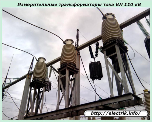
The rated values of the secondary currents of energy measuring transformers are 5 amperes for equipment up to 110 kV inclusive and 1 A higher.
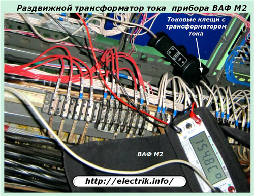
Current transformers are widely used in measuring instruments. Due to the use of the design of the sliding magnetic circuit, it is possible to quickly perform various measurements without breaking the electric circuit, which must be done using conventional ammeters.
Current clamp with sliding magnetic current transformer allow you to grasp any conductor with voltage and measure the magnitude and angle of the current vector.
Voltage transformers
A distinctive feature of these structures is that they operate in a mode close to the idle state, when the magnitude of their output load is low. They are connected to the voltage system, the value of which will be measured.
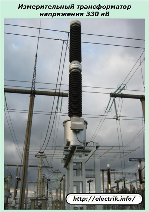
Measuring voltage transformers provide galvanic isolation of the equipment of primary and secondary circuits, operate in each phase of high-voltage equipment.
From them create entire complexes of measurement systems that allow you to filter and highlight the various components of the voltage vectors, the account of which is necessary for the precise operation of the protections, interlocks, alarm systems.
Due to the operation of current and voltage transformers, the vectors of secondary quantities are proportional to the primary in real time. This makes it possible not only to create measurement and protection circuits for current and voltage, but also to analyze the state of powers and resistances in the existing electrical system due to mathematical transformations of vectors.
Special types of transformers
This group includes:
-
separation;
-
matching;
-
high frequency;
-
welding and other types of transformer devices designed to perform special electrical tasks.
Isolation transformers
Placing two windings of exactly the same design on a common magnetic circuit allows you to get the same output voltage from 220 volts 50 hertz at the input.
The question begs: why do such a transformation? The answer is simple: in order to ensure electrical safety.
When the insulating layer of the primary circuit wire is broken, a dangerous potential appears on the device body, which, through a randomly formed circuit through the earth, can hit a person, cause him an electric injury.
The galvanic separation of the circuit makes it possible to optimally use the power supply of electrical equipment and at the same time eliminates the possibility of injuries in the event of breakdowns in the insulation of the secondary circuit to the housing.
therefore isolation transformers widely used where work with a power tool requires additional safety measures. They are also widely used in medical equipment that allows direct contact with the human body.
High frequency transformers
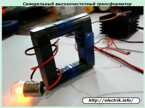
They differ from ordinary ones in the material of the magnetic circuit, which, unlike ordinary transformer iron, is capable of transmitting high-frequency signals without distortion.
The principle of their work is demonstrated by a photograph of a simple home-made construction on ferrites.
Matching Transformers
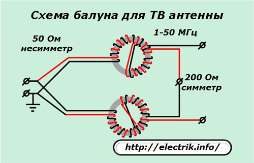
The main purpose is the coordination of the resistances of different parts in electronic circuits. Matching transformers are widely used in antenna devices and amplifier designs on electronic tubes of sound frequencies.
Welding transformers
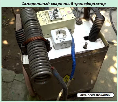
The primary winding is created with a large number of turns, allowing normal processing of electrical energy with an input voltage of 220 or 380 volts. In the secondary winding, the number of turns is much smaller, and the current flowing through them is high. It can reach thousands of amperes.
Therefore, the thickness of the wire of this circuit is selected increased cross-section. There are many different ways to control welding current.
Welding transformers work in large quantities in industrial plants and are popular among fans of making various home-made products.
The types of transformers considered are the most common. Other similar devices that perform special tasks of technological processes work in electrical circuits.
See also at bgv.electricianexp.com
:
