Categories: Featured Articles » Novice electricians
Number of views: 92764
Comments on the article: 0
Connection of an ammeter and a voltmeter in a direct and alternating current network
D.C does not change direction in time. An example is a battery in a flashlight or a radio, a battery in a car. We always know where the positive stigma of the power source is and where it is negative.
Alternating current Is a current that changes direction of movement with a certain periodicity. Such current flows in our outlet when we connect a load to it. There is no positive and negative pole, but only phase and zero. The voltage at zero is close in potential to ground potential. The potential at the phase output changes from positive to negative with a frequency of 50 Hz, which means that the current under load will change its direction 50 times per second.
During one period of oscillation, the current increases from zero to maximum, then decreases and passes through zero, and then the reverse process takes place, but with a different sign.
Receiving and transmitting AC is much simpler than direct: less energy loss. With the help of transformers, we can easily change the AC voltage.
When transmitting a large voltage, less current is required for the same power. This allows for a more subtle argument. In welding transformers, the reverse process is used - they lower the voltage to increase the welding current.
Direct current measurement
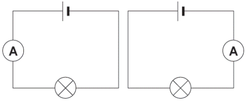
To in an electrical circuit measure current, it is necessary to turn on the ammeter or milliammeter in series with the power receiver. Moreover, in order to exclude the influence of the measuring device on the operation of the consumer, ammeter must have a very small internal resistance, so that it could practically be taken equal to zero, so that the voltage drop across the device could simply be neglected.
The inclusion of an ammeter in the circuit is always in series with the load. If you connect the ammeter parallel to the load, parallel to the power source, then the ammeter simply burns or burns the source, since all the current will flow through the meager resistance of the measuring device.
Shunt
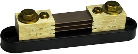
The limits of measurement of ammeters designed for measurements in DC circuits are expandable by connecting the ammeter not directly to the measuring coil in series with the load, but by connecting the measuring coil of the ammeter parallel to the shunt.
So through the coil of the device always only a small part of the measured current passes, the main part of which flows through a shunt connected in series to the circuit. That is, the device will actually measure the voltage drop at the shunt of a known resistance, and the current will be directly proportional to this voltage.
In practice, the ammeter will work as a millivoltmeter. Nevertheless, since the scale of the device is graduated in amperes, the user will receive information about the magnitude of the measured current. The bypass coefficient is usually chosen to be a multiple of 10.
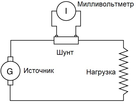
Shunts designed for currents up to 50 amperes are mounted directly in the instrument housings, and shunts for measuring high currents are made remote, and then the device is connected to the shunt with probes. For instruments designed for continuous operation with a shunt, the scales are immediately graded in specific current values taking into account the shunt coefficient, and the user no longer needs to calculate anything.
If the shunt is external, then in the case of a calibrated shunt, the rated current and rated voltage are indicated on it: 45 mV, 75 mV, 100 mV, 150 mV.For current measurements, a shunt is chosen so that the arrow deviates a maximum - the entire scale, that is, the nominal voltages of the shunt and the measuring device should be the same.
If we are talking about an individual shunt for a particular device, then everything, of course, is simpler. According to accuracy classes, shunts are divided into: 0.02, 0.05, 0.1, 0.2 and 0.5 - this is the permissible error in fractions of a percent.
Shunts are made of metals with a low temperature coefficient of resistance, and with significant resistivity: constantan, nickel, manganin, so that when the current flowing through the shunt heats it, this would not affect the readings of the device. To reduce the temperature factor during measurements, an additional resistor from a material of the same kind is included in series with the coil of the ammeter.
DC voltage measurement
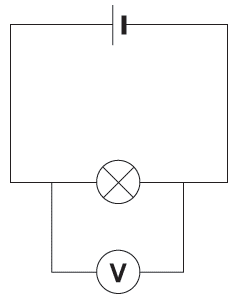
To measure constant voltage between two points of the circuit, parallel to the circuit, between these two points, connect a voltmeter. The voltmeter is always turned on parallel to the receiver or source. And so that the connected voltmeter does not affect the operation of the circuit, does not cause a decrease in voltage, does not cause losses, it must have a sufficiently high internal resistance so that the current through the voltmeter can be neglected.
Additional resistor
And in order to expand the measurement range of the voltmeter, an additional resistor is connected in series with its working winding so that only part of the measured voltage falls directly on the measuring winding of the device, in proportion to its resistance. And with the known value of the resistance of the additional resistor, the total measured voltage acting in this circuit is easily determined by the voltage recorded on it. This is how all classic voltmeters work.
The coefficient resulting from the addition of an additional resistor will show how many times the measured voltage is greater than the voltage per measuring coil of the device. That is, the measurement limits of the device depend on the value of the additional resistor.
An additional resistor is built into the device. To reduce the influence of ambient temperature on the measurements, an additional resistor is made of a material with a low temperature coefficient of resistance. Since the resistance of the additional resistor is many times greater than the resistance of the device, the resistance of the measuring mechanism of the device as a result does not depend on temperature. The accuracy classes of the additional resistors are expressed in the same way as the accuracy classes of shunts - in percent fractions the error value is indicated.
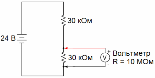
To further expand the measurement range of voltmeters, voltage dividers are used. This is done so that when measuring the voltage on the device corresponds to the nominal value of the device, that is, it would not exceed the limit on its scale. The dividing factor of the voltage divider is the ratio of the input voltage of the divider to the output, the measured voltage. The division coefficient is taken equal to 10, 100, 500 or more, depending on the capabilities of the used voltmeter. The divider does not introduce a large error if the resistance of the voltmeter is also high and the internal resistance of the source is small.
AC measurement
To accurately measure the AC parameters with the instrument, a measuring transformer is required. The measuring transformer used for measurement purposes also provides personnel with safety, since the transformer achieves galvanic isolation from the high voltage circuit. In general, safety precautions prohibit the connection of electrical appliances without such transformers.
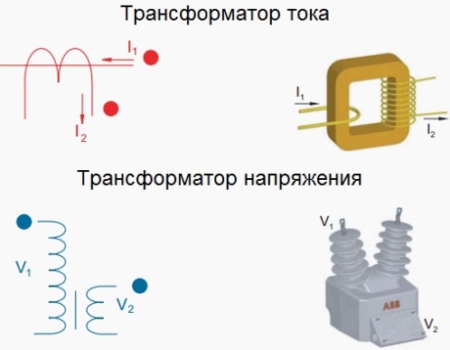
The use of measuring transformers allows you to expand the limits of measurement of devices, that is, it becomes possible to measure large voltages and currents using low-voltage and low-current devices. So, measuring transformers are of two types: voltage transformers and current transformers.
Voltage transformer
A voltage transformer is used to measure alternating voltage. This is a step-down transformer with two windings, the primary winding of which is connected to two points of the circuit, between which you need to measure the voltage, and the secondary - directly to the voltmeter. Measuring transformers in the diagrams are depicted as ordinary transformers.
A transformer without a loaded secondary winding operates in idle mode, and when a voltmeter is connected, the resistance of which is high, the transformer remains practically in this mode, and therefore the measured voltage can be considered proportional to the voltage applied to the primary winding, taking into account the transformation coefficient equal to the ratio of the number of turns in its secondary and primary windings.
In this way, a high voltage can be measured, while a small safe voltage is applied to the device. It remains to multiply the measured voltage by the transformation coefficient of the voltage measuring transformer.
Those voltmeters that were originally designed to work with voltage transformers have a graduation of the scale taking into account the transformation coefficient, then the value of the changed voltage is immediately visible on the scale without additional calculations.
In order to increase safety when working with the device, in case of damage to the insulation of the measuring transformer, one of the terminals of the secondary winding of the transformer and its frame are first grounded.
Measuring Current Transformers
Measuring current transformers are used to connect ammeters to AC circuits. These are double-winding step-up transformers. The primary winding is connected in series to the measured circuit, and the secondary to the ammeter. The resistance in the ammeter circuit is small, and it turns out that the current transformer operates almost in the short circuit mode, while it can be assumed that the currents in the primary and secondary windings relate to each other as the number of turns in the secondary and primary windings.
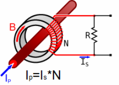
By selecting a suitable ratio of turns, significant currents can be measured, while currents that are sufficiently small will always flow through the device. It remains to multiply the current measured in the secondary winding by the transformation coefficient. Those ammeters that are designed for continuous operation together with current transformers have a graduation of scales taking into account the transformation coefficient, and the value of the measured current can easily be read off the scale of the device without calculations. In order to increase personnel safety, one of the terminals of the secondary winding of the measuring current transformer and its frame are first grounded.
In many applications, bushing measuring current transformers are convenient, in which the magnetic circuit and the secondary winding are isolated and located inside the bushing, through the window of which a copper bus with a measured current passes.
The secondary winding of such a transformer is never left open, because a strong increase in the magnetic flux in the magnetic circuit can not only lead to its destruction, but also induce EMF that is dangerous for personnel on the secondary winding. In order to carry out a safe measurement, the secondary winding is shunted with a resistor of known rating, the voltage at which will be proportional to the measured current.
Two types of errors are characteristic of measuring transformers: angular and transformation coefficient. The first is associated with a deviation of the phase angle of the primary and secondary windings from 180 °, which leads to inaccurate readings of the wattmeters.As for the error associated with the transformation coefficient, this deviation shows the accuracy class: 0.2, 0.5, 1, etc., as a percentage of the nominal value.
See also at i.electricianexp.com
:
