Categories: Featured Articles » Novice electricians
Number of views: 36393
Comments on the article: 0
Methods for connecting electrical energy receivers
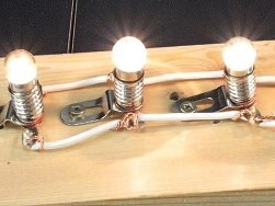 With the simultaneous inclusion of several power receivers in the same network, these receivers can easily be considered simply as elements of a single circuit, each of which has its own resistance.
In some cases, this approach turns out to be quite acceptable: incandescent lamps, electric heaters, etc. - can be perceived as resistors. That is, the devices can be replaced by their resistance, and it is easy to calculate the parameters of the circuit.
The method of connecting the power receivers can be one of the following: serial, parallel or mixed type of connection.
Serial connection

When several receivers (resistors) are connected in a serial circuit, that is, the second output of the first is connected to the first output of the second, the second output of the second is connected to the first output of the third, the second output of the third with the first output of the fourth, etc., when connecting such a circuit to the power source, through all elements of the circuit current I will flow of the same magnitude. This idea is explained in the figure.
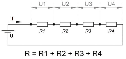
Replacing the devices with their resistances, we transform the figure into a circuit, then the resistances R1 to R4, connected in series, will each take on certain voltages, which in total will give the EMF value at the terminals of the power source. For simplicity, hereinafter we will depict the source in the form of a galvanic cell.
Expressing the voltage drop through the current and through the resistance, we obtain the expression for the equivalent resistance of the series circuit of the receivers: the total resistance of the series connection of resistors is always equal to the algebraic sum of all the resistances that make up this circuit. And since the voltages in each of the sections of the circuit can be found from Ohm's law (U = I * R, U1 = I * R1, U2 = I * R2, etc.) and E = U, then for our circuit we get:

The voltage at the terminals of the power supply is equal to the sum of the voltage drops at each of the series-connected receivers that make up the circuit.
Since the current flows through the entire circuit of the same value, it will be fair to say that the voltages at the series-connected receivers (resistors) are related in proportion to the resistances. And the higher the resistance, the higher the voltage applied to the receiver.
For a series connection of resistors in the amount of n pieces having the same resistances Rk, the equivalent total resistance of the circuit as a whole will be n times greater than each of these resistances: R = n * Rk. Accordingly, the voltages applied to each of the circuit resistors will be equal to each other, and will be n times less than the voltage applied to the entire circuit: Uk = U / n.

The following properties are characteristic for the series connection of power receivers: if you change the resistance of one of the circuit receivers, then the voltages at the other circuit receivers will change; when one of the receivers breaks, the current will stop in the entire circuit, in all other receivers.
Due to these features, serial connection is rare, and is used only where the mains voltage is higher than the rated voltage of the receivers, in the absence of alternatives.
For example, with a voltage of 220 volts, you can power two series-connected lamps of equal power, each of which is designed for a voltage of 110 volts. If these lamps at the same rated supply voltage have different rated power, one of them will be overloaded and most likely will instantly burn out.
Parallel connection

The parallel connection of the receivers involves the inclusion of each of them between a pair of points of the electric circuit so that they form parallel branches, each of which is powered by the voltage of the source. For clarity, we will again replace the receivers with their electrical resistances in order to obtain a circuit according to which it is convenient to calculate the parameters.
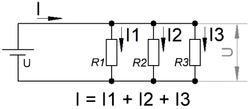
As already mentioned, in the case of a parallel connection, each of the resistors experiences the same voltage. And in accordance with Ohm's law, we have: I1 = U / R1, I2 = U / R2, I3 = U / R3.
Here I is the source current. The first Kirchhoff law for this circuit allows us to write the expression for the current in its unbranched part: I = I1 + I2 + I3.
Hence, the total resistance for parallel connection of circuit elements to each other can be found from the formula:

The reciprocal of the resistance is called the conductivity G, and the formula for the conductivity of the circuit, consisting of several elements connected in parallel, can also be written: G = G1 + G2 + G3. The conductivity of the circuit in the case of parallel connection of the resistors forming it is equal to the algebraic sum of the conductivities of these resistors. Therefore, when parallel receivers (resistors) are added to the circuit, the total resistance of the circuit will decrease, and the total conductivity will increase accordingly.
The currents in the circuit consisting of parallel-connected receivers are distributed between them in direct proportion to their conductivities, that is, inversely proportional to their resistances. Here we can give an analogy from hydraulics, where the water flow is distributed through the pipes in accordance with their sections, then a larger section is similar to a lower resistance, that is, a greater conductivity.
If the circuit consists of several (n) identical resistors connected in parallel, then the total resistance of the circuit will be n times lower than the resistance of one of the resistors, and the current through each of the resistors will be n times less than the total current: R = R1 / n; I1 = I / n.
A circuit consisting of parallel-connected receivers connected to a power source is characterized in that each of the receivers is energized by the power source.
For an ideal source of electricity, the statement is true: when connecting or disconnecting resistors in parallel to the source, the currents in the remaining connected resistors will not change, that is, if one or more receivers of the parallel circuit fail, the rest will continue to work in the same mode.
Due to these features, a parallel connection has a significant advantage over a serial one, and for this reason it is a parallel connection that is most common in electrical networks. For example, all electrical appliances in our homes are designed to be connected to a household network in parallel, and if you disconnect one, it won’t harm the rest.
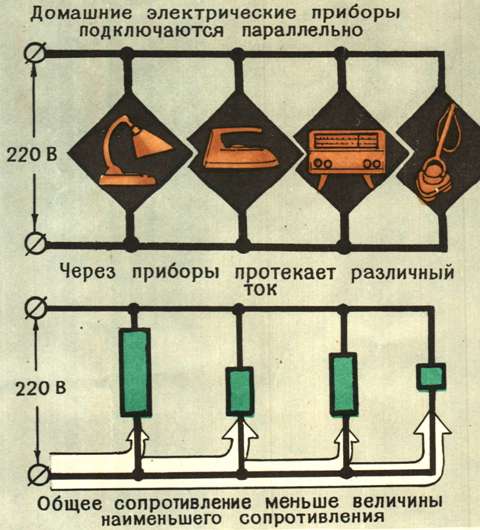
Comparison of serial and parallel circuits
Mixed compound
A mixed connection of receivers is understood to mean such a connection when a part or several of them are connected in series, and another part or several in parallel. Moreover, the entire chain can be formed from different compounds of such parts between themselves. For example, consider the scheme:
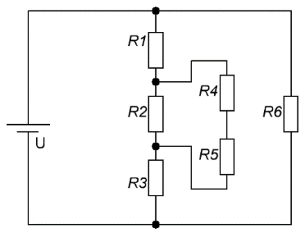
Three series-connected resistors are connected to a power source, two more are connected in parallel to one of them, and the third is connected in parallel to the entire circuit.To find the impedance of the circuit, they go through successive transformations: a complex circuit is sequentially led to a simple form, sequentially calculating the resistance of each link, and so find the total equivalent resistance.

For our example. First, the total resistance of the two resistors R4 and R5 connected in series is found, then the resistance of their parallel connection with R2, then they are added to the obtained value of R1 and R3, and then the resistance value of the entire circuit, including the parallel branch R6, is calculated.
Various methods of connecting power receivers are used in practice for various purposes in order to solve specific tasks. For example, a mixed compound can be found in soft charge circuits. electrolytic capacitors in powerful power supplies, where the load (capacitors after the diode bridge) first receives power in series through the resistor, then the resistor is bridged by the relay contacts, and the load is connected to the diode bridge in parallel.
See also at bgv.electricianexp.com
:
