Categories: Featured Articles » Novice electricians
Number of views: 128717
Comments on the article: 4
Calculation of short circuit currents for beginner electricians
When designing any energy system, specially trained electrical engineers using technical manuals, tables, graphs and computer programs perform its analysis on the operation of the circuit in various modes, including:
1. idling;
2. rated load;
3. emergency situations.
A special danger is the third case when a network malfunctions occur that can damage the equipment. Most often, they are associated with “metallic” shorting of the supply circuit, when electrical resistances with a dimension of a fraction of Ohm are randomly connected between different potentials of the input voltage.
Such modes are called short-circuit currents or abbreviated as "short circuit". They occur when:
-
failures in the operation of automation and protection;
-
staff errors;
-
damage to equipment due to technical aging;
-
natural impacts of natural phenomena;
-
sabotage or vandal actions.
Short-circuit currents are significantly greater in magnitude than the rated loads under which an electrical circuit is created. Therefore, they simply burn out weak spots in the equipment, destroy it, cause fires.
In addition to thermal destruction, they still have a dynamic effect. Its manifestation shows the video well:
In order to exclude the development of such accidents during operation, they begin to struggle with them even at the stage of creating the project of electrical equipment. To do this, theoretically calculate the possibility of occurrence of short circuit currents and their magnitude.
This data is used to further create the project and select the power elements and protective devices of the circuit. They continue to work with them constantly during the operation of equipment.
The currents of possible short circuits are calculated by theoretical methods with varying degrees of accuracy acceptable for the reliable creation of protections.
What electrical processes are the basis for calculating short circuit currents
Initially, we will focus on the fact that any type of applied voltage, including direct, alternating sinusoidal, pulsed, or any other random one, creates accident currents that repeat the image of this form or change it depending on the applied resistance and the action of side factors. All this must be provided to designers and taken into account in their calculations.
Assessment of the occurrence of m action of short circuit currents allows you to perform:
-
Ohm's law;
-
the magnitude of the power characteristic of the power applied from the voltage source;
-
structure of the electrical circuit used;
-
value of the total applied resistance to the source.
Ohm's Law
The basis for calculating short circuits is the principle that determines that the current strength can be calculated by the value of the applied voltage, if you divide it by the value of the connected resistance.
It also acts in the calculation of rated loads. The only difference is that:
-
during the optimal operation of the electrical circuit, the voltage and resistance are practically stabilized and vary slightly within the limits of the working technical standards;
-
in case of accidents, the process occurs spontaneously at random. But it can be foreseen, calculated by the developed methods.
Power supply voltage
With its help, the power energy possibility of performing destructive work by short-circuit currents is evaluated, the duration of their course, the value are analyzed.
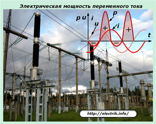
Let's look at an example when one and the same piece of copper wire with a cross section of one and a half square mm and a length of half a meter was first connected directly to the Krona battery terminals, and after a while they inserted a household outlet into the phase and zero contacts.
In the first case, a short circuit current will flow through the wire and the voltage source, which will warm the battery to a state that will damage its performance. The power of the source is not enough to burn the connected jumper and break the circuit.
In the second case, automatic protection will work. Suppose that they are all faulty and jammed. Then the short circuit current will pass through the home wiring, will reach the input shield to the apartment, the entrance, the building and will reach the power transformer substation via cable or overhead power lines.
As a result, a fairly long circuit with a large number of wires, cables and places of their connection is connected to the transformer winding. They will significantly increase the electrical resistance of our short circuit. But even in this case, it is highly likely that it will not withstand the applied power and simply burn out.
Circuit configuration
When consumers are fed, voltage is supplied to them in different ways, for example:
-
through the potentials of the positive and negative terminals of the DC voltage source;
-
phase and zero of a single-phase household network 220 volts;
-
a three-phase circuit of 0.4 kV.
In each of these cases, insulation failures can occur in various places, which will lead to the flow of short circuit currents through them. For a three-phase AC circuit only, short circuits between:
-
all three phases simultaneously - is called three-phase;
-
any two phases between themselves - interphase;
-
any phase and zero - single-phase;
-
phase and ground - single phase to ground;
-
two phases and ground - two phase to ground;
-
three phases and ground - three phase to ground.
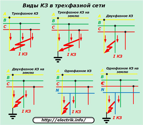
When creating a project for the power supply of equipment, all these modes must be calculated and taken into account.
The effect of electrical resistance of a circuit
The length of the line from the voltage source to the location of the short circuit has a certain electrical resistance. Its value limits short-circuit currents. The presence of transformer windings, chokes, coils, capacitor plates add inductive and capacitive resistances, forming aperiodic components that distort the symmetrical shape of the fundamental harmonics.
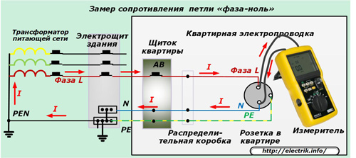
Existing methods for calculating short-circuit currents allow them to be calculated with sufficient accuracy for practice according to previously prepared information. The actual electrical resistance of an already assembled circuit can be measured by the method phase zero loops. It allows you to clarify the calculation, make adjustments to the choice of defenses.
Basic documents for the calculation of short circuit currents
1. The method of calculating the short circuit currents
It is well stated in the book of A. V. Belyaev “The choice of equipment, protections and cables in 0.4 kV networks”, released by Energoatomizdat in 1988. Information occupies 171 pages.
The book provides:
-
sequence of calculation of short circuit currents;
-
taking into account the current-limiting effect of the electric arc at the site of damage;
-
principles for the selection of protective equipment according to the values of the calculated currents.
The book publishes reference information on:
-
circuit breakers and fuses with analysis of the characteristics of their protective properties;
-
selection of cables and equipment, including installations for protecting electric motors, power assemblies, input devices of generators and transformers;
-
disadvantages of protection of certain types of circuit breakers;
-
features of the use of remote relay protection;
-
examples of solving design problems.
You can download this book here: Selection of equipment, shields and cables in 0.4 kV networks
2. Guidelines RD 153—34.0—20.527—98
This document defines:
-
methods for calculating short-circuit currents of symmetric and asymmetric modes in electrical installations with voltages up to and above 1 kV;
-
methods for checking electrical apparatus and conductors for thermal and electrodynamic resistance;
-
test methods for the switching ability of electrical devices.
The instructions do not cover the calculation of short-circuit currents with respect to relay protection devices with specific operating conditions.
You can download them here: Guidelines for the calculation of short-circuit currents
3. GOST 28249-93
The document describes the short circuits that occur in electrical installations of alternating current and the procedure for their calculation for systems with voltages up to 1 kV. It has been effective since January 1, 1995 in the territories of Belarus and Kyrgyzstan. Moldova, Russia, Tajikistan, Turkmenistan and Ukraine.
The state standard defines general methods for calculating short-circuit currents at the initial and any arbitrary time moment for electrical installations with synchronous and asynchronous machines, reactors and transformers, overhead and cable power lines, busbars, nodes of complex complex load.
Technical standards for the design of electrical installations are determined by current state standards and agreed by the Interstate Council for Standardization, Metrology, and Certification.
Download GOST 28249-93 (2003). Short circuits in electrical installations. Calculation methods in AC electrical installations with voltage up to 1 kV can be here: GOST for the calculation of short-circuit currents
The sequence of actions of the designer for the calculation of short circuit currents
Initially, you should prepare the information necessary for analysis, and then carry out the calculation. After installation of the equipment for the process of putting it into operation and during operation, the correct selection and operability of the protections is checked.
Source data collection
Any scheme can be reduced to a simplified form when it consists of two parts:
1. voltage source. For a 0.4 kV network, its role is played by the secondary winding of the power transformer;
2. The power line.
Under them are collected the necessary characteristics.
Transformer data for the calculation of short-circuit currents
Find out:
-
value of short circuit voltage (%) - Uкз;
-
short circuit loss (kW) - Rk;
-
rated voltages on the high and low side windings (kV. V) - Uvn, Unn;
-
phase voltage on the low side winding (V) - Ef;
-
rated power (kVA) - Snt;
-
total current resistance of single-phase short-circuit (mOhm) - Zt.
Supply line data for calculating short-circuit currents
These include:
-
marks and quantity of cables with indication of material and section of veins;
-
total length of the route (m) - L;
-
inductive resistance (mOhm / m) - X0;
-
impedance for the phase-zero loop (mOhm / m) - Zpt.
This information for the transformer and the line is concentrated in the directories. Kud impact coefficient is also taken there.
Calculation sequence
According to the found characteristics, they are calculated for:
-
transformer - active and inductive resistance (mOhm) - Rt, Xt;
-
lines - active, inductive and impedance (mOhm).
These data allow you to calculate the total active and inductive resistance (mOhm). And based on them, you can determine the total resistance of the circuit (mOhm) and currents:
-
three-phase circuit and shock (kA);
-
single-phase short circuit (kA).
According to the values of the last calculated currents, they select circuit breakers and other protective devices for consumers.
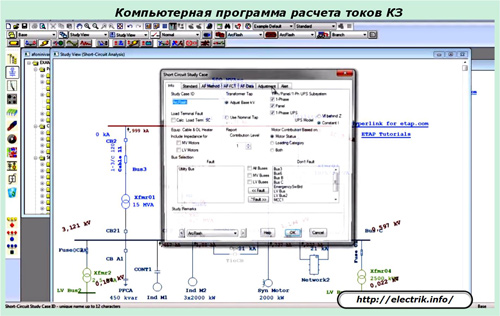
Designers can perform the calculation of short-circuit currents manually according to formulas, look-up tables and graphs, or using special computer programs.
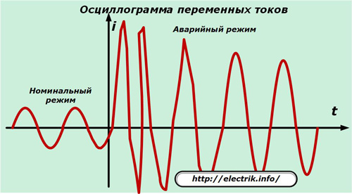
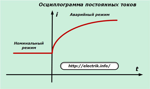
On real power equipment put into operation, all currents, including rated and short circuits, are recorded by automatic oscilloscopes.
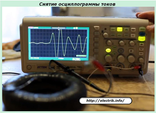
Such oscillograms allow you to analyze the course of the emergency conditions, the correct operation of power equipment and protective devices.They take effective measures to improve the reliability of consumers of the electrical circuit.
See also at i.electricianexp.com
:

