Categories: Featured Articles » Novice electricians
Number of views: 10242
Comments on the article: 0
Automatic switches of the A3700 HEMZ series
 One of the most popular series of circuit breakers for high currents (up to 630 A) in power supply systems are A3700 series circuit breakers. Automatic machines are available unipolar, bipolar and three-pole. A3700 series automatic machines are designed for current protection of electrical equipment during current overloads and short circuits in a wide variety of AC and DC electric circuits with a rated voltage of up to 660 V (for alternating current) and up to 440 V (for direct current).
Circuit breakers can also be used for infrequent switching of electrical circuits, as well as for protecting these circuits when the voltage drops below unacceptable values. Current protection releases are performed on semiconductor and electromagnetic elements. The mechanical wear resistance of A3700 circuit breakers is 16,000 on-off cycles, switching wear resistance is 10,000 for current-limiting and 5,000 cycles for time-delayed automatic machines.
Automatic machines are issued in selective execution. Response time in the short circuit zone adjustable within 0.1 - 0.4 s. For selective protection, switches 3 and 4 are available, and their maximum current protection is carried out exclusively on semiconductor releases. The presence of such a release allows a quick restart after the circuit breaker disconnects the emergency current, and also allows you to change the response time of the electromagnetic release.
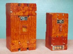
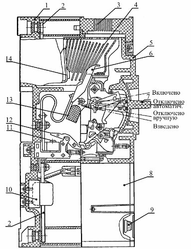
The circuit breaker of the A3700 series (Fig. 1) is made in a special insulating shell, which consists of a housing 1 and a cover 5. The fins in the apparatus body separate the poles relative to each other.

Fig. 1. Circuit breaker A3700 series
The current leads 2 are closed from touching. The contact system of the machine consists of movable power contacts 6, which are fixed on the insulating axis 13, associated with a special tripping device and fixed power contacts 14 of the current-limiting device.
The arc is extinguished in the arcing chamber 4. An arc extinguishing grid is used to extinguish the arc. Semiconductor releases are made in the form of a special unit 8. Using the handles 9, you can adjust the rated current of the circuit-breaker release, the current setting in the short-circuit zone.
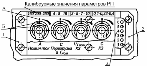
Figure 2 shows the front panel of the semiconductor release control unit.

Fig. 2. Front panel of the control unit for the semiconductor release
The control unit itself is an independent replaceable unit having its own plastic case, and which contains all its elements. On the front side of the control unit are removable transparent covers. Under the cover 1 there are knobs for adjusting the parameters of the semiconductor release, and under the cover 2 there are sockets for checking the operation of the release.
Under each adjusting knob there are abbreviated inscriptions:
-
A nominee. current - under the handle for regulating the rated current of the machine;
-
With overload 5Inom - under the knob to adjust the setpoint according to the response time in the area of overload currents;
-
I / IMr. KZ - under the handle for adjusting the setpoint for the operating current in the zone of short-circuit currents;
-
With short circuit - under the handle to adjust the setpoint but the response time in the zone of short-circuit currents (current-limiting switches of this handle do not have).
Above each adjustment knob are numbers and risks A, corresponding to calibrated parameter values. Each adjustment knob has a risk B.
In order to adjust the semiconductor release to the desired parameter value, it is necessary to remove cover 1 (Fig. 2) and, by turning the corresponding adjustment knob, combine risk B with risk A. Here it must be taken into account that when adjusting, first turn the adjustment knob clockwise to the stop, and then turn it counterclockwise to the desired position. It is not allowed to establish risk B outside the sector limited by extreme risks A.
The power supply for the control unit of the semiconductor release of the AC circuit breaker is provided by current transformers, and the DC circuit breaker is supplied through a block of quenching resistors or magnetic sensors. Extinguishing resistors are integrated in the free pole of the switch housing, and sensors in each pole.
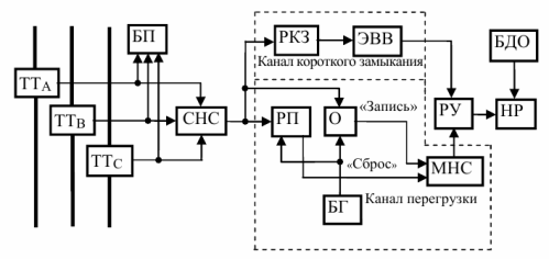
In fig. 3 shows a block diagram of a semiconductor release for a selective circuit breaker. From CT current transformers (measuring element of the circuit), the signals are fed to the SNA circuit, from where the selected signal is fed to the inputs of the overload and short circuit channels.

Fig. 3. Block diagram of a semiconductor release
The overload channel contains BG blocking generators, RP overload relays, one-shot oscillator O, and an MNS magnetic storage counter. The short circuit channel contains a relay RKZ short circuit and an element of time delay EVV. The structure of the circuit also includes a relay amplifier of the RU independent NC release, which acts as an executive body, a remote disconnect unit BDO and a power supply unit.
If there is no overload, the pulses from the output of the blocking generator through the overload relay via the "Reset" channel are fed to the input of the magnetic counter, setting it to its original position. If an overload occurs in the protected circuit that exceeds a predetermined level (set point), an overload relay is activated.
In this case, the arrival of pulses through the "Reset" channel to the counter is stopped, and the pulses from the output of the blocking generator pass to the input via the "Record" channel of the counter with an interval equal to the time delay of the one-shot. The output signal of the magnetic counter, which occurs when it is full, is fed to one of the inputs of the relay amplifier of the RU, acting on an independent trip unit of the automatic machine, which performs a hundred shutdown.
The operation of an independent calculator via a short circuit channel occurs when the current exceeds a predetermined level, determined by the RKZ short circuit relay. The operation of the short circuit relay leads to the operation of the relay amplifier after a period of time, determined by the time delay element of the emulsion explosive.
The power supply unit supplies power to the circuit elements of the semiconductor release and the coil of an independent splitter. The remote shutdown unit BDO is designed for operational shutdown of the machine.
The semiconductor protection block of the circuit breaker A3700 series is operational when the voltage fluctuates within 85 - 110% of the nominal value.
See also at i.electricianexp.com
:
