Categories: Featured Articles » Novice electricians
Number of views: 43785
Comments on the article: 1
Electrolytic capacitors
In practice, every electrician is faced with the work of adapters, power supplies, voltage converters. In all of these devices, electric capacitors are widely used, which are often called “electrolytes” on slang.
Their main advantage is the relatively large size of the capacitance with a relatively small size. In addition, their production has long been established, and the cost is relatively low.
Device principles
Any capacitor consists of two plates, the space between which is filled with a dielectric.
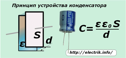
The formula shown in the picture recalls that the capacitance C depends on the area of each plate S, the distance between the plates d and the dielectric constant of the medium inside them ε. The value ε0 is the electric constant that determines the strength of the electric field inside the vacuum.
The electrolytic capacitor differs from all others in that it uses an electrolyte layer that fills the space between the two plates, most often made of foil plates. Moreover, one of them is covered with a small dielectric layer of the oxide film.
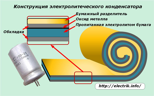
Foil tapes are folded together, separated by a very thin paper pad soaked in electrolyte. Its value of about 1 μm can significantly increase the capacitance of the capacitor. In the above formula for determining C, the thickness of the dielectric layer d is in the denominator.
The top layer of the foil is covered with release paper, and the entire structure is rolled up for placement in a cylindrical body.
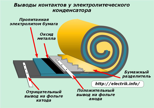
At the ends of the foil, metal plates are welded by cold welding methods, providing contacts for connecting to the electrical circuit as a cathode and anode. Moreover, a positive conclusion is formed on the plate with the oxide layer.
The cathode plays the role of an electrolyte that contacts the entire surface of the second plate.
Since the capacitance of the capacitor depends on the area of the plates, one of the ways to increase it is included in the production technology - this is corrugation of the surface by electrolyte by chemical etching. It can be performed due to chemical erosion or electrochemical corrosion.
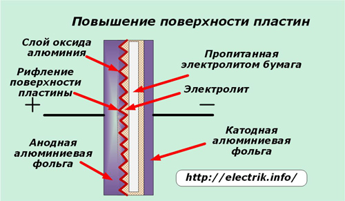
Liquid electrolytes are able to reliably flow into the created microscopic recesses of the anode.
An oxide layer on the foil is created during electrical oxidation. This process occurs when current flows through the electrolyte. The picture below shows the current-voltage characteristic, showing the change in currents inside the device with increasing voltage.
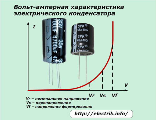
The capacitor operates normally at rated voltage and temperature. If overvoltage occurs, the formation of the oxide layer resumes and a large amount of heat begins to be generated, which leads to gas formation and an increase in pressure inside the sealed enclosure.
Therefore, electrolytic capacitors are capable of exploding, which often happened with old constructions of the times of the USSR, which were carried out in a single case without creating explosion protection. This property often led to damage to other, neighboring equipment elements.
Modern models create a protective membrane, which is destroyed at the beginning of gas formation and this prevents an explosion. It is made in the form of notches of the letters "T", "Y" or the sign "+".
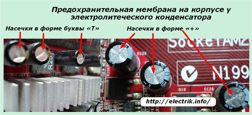
Types of Electrolytic Capacitors
By their design, “electrolytes” refer to polar devices, that is, they must work when the current flows in only one direction. Therefore, they are used in circuits of constant or ripple voltage, taking into account the direction of passage of electric charges.
To operate in sinusoidal current circuits, “non-polar electrolytes” have been created. Due to additional elements in the design, with equal capacity, they have increased dimensions and, accordingly, cost.
The electrolyte between the plates can be used concentrated solutions of various alkalis or acids. According to the method of filling them, capacitors are divided into:
-
liquid;
-
dry
-
oxide metal;
-
semiconductor oxide.
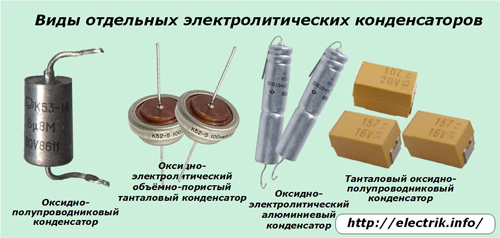
As the material of the anode, a foil of aluminum, tantalum, niobium or sintered powder can be selected. For oxide semiconductor capacitors, the cathode is a semiconductor layer deposited directly on the oxide layer.
Operational Features
The ability of electrolytes to emit gases during heating dictates the need for a capacitor to ensure reliability to create a margin of rated voltage up to 0.5 ÷ 0.6 of its value. This is especially true for use in devices with elevated temperatures.
For capacitors designed for operation in AC voltage circuits, the operating frequency is specified. Usually it is 50 hertz. To work with higher frequency signals, it is necessary to reduce the operating voltage. Otherwise, the dielectric will overheat and breakdown, rupture of the housing.
Electrolytes with a large capacity and low leakage currents are capable of long-term storage of the accumulated charge. For safety reasons, to accelerate their discharge, a resistor with a resistance of 1 MΩ and a power of 0.5 W is connected in parallel with the terminals.
For use in high-voltage devices, capacitors assembled in series circuits are used. To equalize the voltage between them, resistors with a nominal value of 0.2 to 1 MΩ are connected in parallel to the terminals of each.
If it is necessary to use polar electrolytic capacitors in alternating voltage circuits, a circuit is assembled in which the current through each element passes only in one direction. For this use diodes and current limiting resistor.
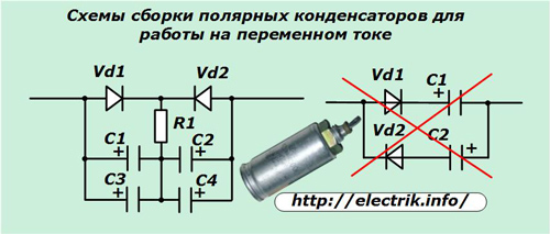
Such circuits were previously assembled to rotate the phase of the current relative to the voltage when starting powerful three-phase asynchronous electric motors from a single-phase network. Now this issue is already losing its former relevance.
The absence of a current-limiting resistor in such a chain leads to overheating of the dielectric layer and the failure of the electrolytic capacitor.
Liquid electrolyte dries through time through defects in the housing. Due to this, the capacity is gradually reduced. Over time, it reaches a critical value. An electrolytic capacitor that has fallen out of operation often causes a breakdown in the electrical device.
Capacitor malfunctions due to violation of equivalent resistance ESR
Electrolytic capacitors have another technical feature that affects its performance during operation. Over time, the capacitor gradually decreases the electrical conductivity between the plates and the terminals due to the constantly occurring internal electrical processes. Its value is estimated by the equivalent active resistance, which is indicated by the ESR index. In Russian, they call EPS: equivalent series resistance.
This arising parasitic characteristic does not affect the operation of electrolytes in circuits with a frequency of up to 50 hertz, using the output winding of the transformer, diode rectification, and a capacitor to smooth out the pulsations. But, in devices using high-frequency signals inside switching power supplies, such an added active resistance in series to the capacitance no longer allows the circuit to work.
A capacitor with increased ERS does not differ in appearance from a working one. It's just that its active resistance increases by more than one Ohm and can reach up to 10 Ohms.
Determination methods
The industry produces instruments that allow to measure this value on the basis of a prototype invented in Russia in the 60s. They allow you to take measurements without evaporating the capacitors from the circuit, work on the principle of bridge resistance meters for alternating current.
Craftsmen create their own simplified designs that allow us to evaluate the health of the capacitor by this parameter based on the determination of the active resistance exceeding 1 Ohm. As a similar indicator, you can assemble a simple device, shown in the diagram.
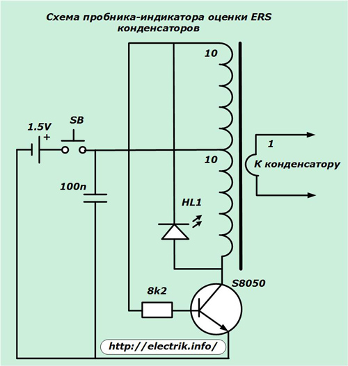
A regular finger-type battery is used to power it. The LED indicates the suitability of the electric capacitor by the ERS parameter by comparing the high-frequency signals on the toroidal transformer coming from the capacitor and the generated oscillating circuit.
The image of the same scheme in a somewhat simplified form is shown below.
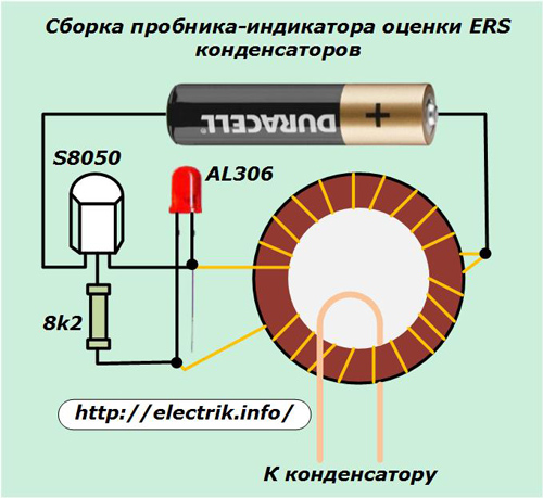
The test capacitor is connected to a winding made in one turn on a transformer of a ferromagnetic core with a magnetic permeability of the order of 800 ÷ 1000. The voltage on this winding does not exceed 200 millivolts, so you can evaluate the characteristics of the electrolyte without soldering from the board.
Such an indicator does not require special settings. It is quite enough to check the glow of the LED on the control resistor of one ohm and navigate it in future measurements. The transistor can be used by anyone with a collector current of 100 mA and a gain of more than 50.
Such a probe will not work accurately with capacitors having a capacitance of less than 100 μF.
Ionistor - supercapacitor
A kind of capacitor with an electrolyte that provides the flow of electrochemical processes is ionistor. It uses the effect of a double electric layer that occurs when the lining material comes into contact with the electrolyte and combines the functions of a capacitor with a chemical current source.
Its design is shown in the picture.
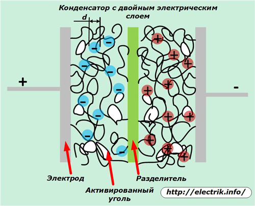
Here, the thickness of the formed double layer is very small. This allows you to significantly increase the capacity of the ionistor. Also, it is easier for these capacitors to increase the area of the contact surface of the plates. They are made from porous materials, for example, activated carbon, foamed metals.
The capacity of the ionistor can reach several farads with a voltage on the plates up to 10 volts. He recruits it in a short time and then reliably saves it. Therefore, these models are used to backup various power supplies.
Operating conditions greatly affect the duration of the operational state of the ionistor. If the operating temperature does not exceed 40 degrees, and the voltage is 60% of the nominal, then the resource can be more than 40,000 hours.
It is only necessary to increase its heating to 70 degrees, and the voltage - up to 80%, as the battery life is reduced to 500 hours. Ionists find a wide variety of applications in everyday life. They work in sets of solar panels, car radio equipment, smart home automation.
The South Korean automobile manufacturer Hyundai Motor Company is working on the production of electric buses powered by ionistors. Their charge is planned to be performed during short stops on the route of movement.
At its core, this type of transport completely replaces the trolley bus, which excludes the entire contact wire network from work.
See also at bgv.electricianexp.com
:
