Single-phase induction motor control device
 The proposed device can be used to control single-phase asynchronous motors, in particular, for starting and braking an asynchronous motor (HELL) with a short-circuited rotor of low power, having a starting winding or starting capacitor, disconnected before the end of the start. It is possible to use the device to start more powerful asynchronous motors, as well as to start three-phase motors operating in single-phase mode.
In the known device, repeated normal start-up is possible only after cooling of the thermistor and the braking mode of the robot is not provided. The proposed device has wider functionality.
The device contains a two-pole switch SA1 for two positions, with the help of which the working winding P of the induction motor and the winding of the electromagnetic relay K1 are connected through the rectifier diode VD1, the RC timing circuit, consisting of a parallel connected resistor R1 and an electrolytic capacitor C1. The closing contact K1.1 relay K1 is used to connect the starting winding II HELL to the mains through the phase-shifting element C2 and switch SA1.
In the starting position, the coil of the electromagnetic relay ...
How to make a do-it-yourself indicator of connecting electrical appliances to a 220V network
 Indication device allows you to monitor when leaving home: are electrical appliances disconnected from the network? If any load with a power> 8 W remains on, then both LEDs HL1 and HL2 light up (see figure). The brightness of the glow is small at a load of 8 watts (a dot in the LED is on), therefore, in bright light, to see the glow, you need to cover with your palm the penetration of bright light on the LED. LED (s) are installed at the front door. Conductors to them (0.2 mm) are laid under the wallpaper (due to the small current passing through them). LED HL2 can be excluded from the circuit, and if it remains, then HL1 can be installed on the inside of the door, and HL2 - on the outside.
As a T1 transformer, ready-made ones are used, which have a winding with a large number of turns (2000-3000, or maybe less) and it is possible to wind 8 to 10 turns of a mounting wire of sufficient cross-section. In each particular transformer, the number of turns is selected experimentally. These 8 - 10 turns will be the primary winding of the transformer, and the secondary - those that are in the finished transformer ...
How to make a simple status indicator of a remote lamp
 At one time, I was faced with the need to control the burning and integrity of the light bulb when the switch is in another room (for example, a basement, cellar or chicken coop). More than once it happened, the switch is turned on, and the light does not light up: it either burned out, or the contact in the cartridge or switch disappeared. In this case, the switch is located in the corridor, and to the basement, where hens live, you need to go around the house. It is especially bad when, because of this, the bird does not enter the basement in the evening, and then it must be entered manually. The problem was solved by installing a simple and trouble-free device that indicates the flow of current in the circuit of the lighting lamp and is located near the switch.
The indicator diagram is shown in the figure. When current flows through ballast diodes, a voltage sufficient for the LED to glow is incident on them. You can connect the device at any convenient point in the electrical circuit (before or after the switch) or to break the second wire leading to the lamp.
The indicator is not critical to details. As ballast diodes, you can use any small-sized diodes with an allowable direct current not lower than the current consumption of the illuminator and any operating voltage ...
How to easily control a powerful AC load
 Sometimes you need a weak signal from the microcontroller to turn on a powerful load, such as a lamp in the room. This problem is especially relevant for smart home developers. The first thing that comes to mind is a relay. But do not rush, there is a better way :)
In fact, the relay is a continuous hemorrhage. Firstly, they are expensive, and secondly, to power the relay coil, an amplifying transistor is needed, since the weak leg of the microcontroller is not capable of such a feat. Well, and thirdly, any relay is a very bulky design, especially if it is a power relay designed for high current.
If we are talking about alternating current, then it is better to use triacs or thyristors. What it is? And now I’ll tell you.
If on the fingers, then the thyristor is similar to a diode, even the designation is similar. Passes current in one direction and does not let in the other. But he has one feature that distinguishes it from the diode radically - the control input.
If the opening current is not applied to the control input, the thyristor will not pass current even in the forward direction. But it is worth giving at least a brief impulse, as it immediately opens and remains open as long as there is direct voltage. If the voltage is removed or polarity reversed, the thyristor will close ...
Home-made device for protecting the motor from under-phase conditions and overload
 As typical elements of motor protection, electrothermal relays are most often used. Designers are forced to overestimate the rated current of these relays, so that there are no trips at startup. The reliability of such protection is low, and a large percentage of engines fail during operation.
The circuit of the motor protection device (see the figure) from out-of-phase modes and overload is characterized by increased reliability. Transistors VT1, VT2 together with the elements connected to them form an analog of a dynistor, the switching voltage of which (Uin) depends on the ratio R6 / R7. With the ratings indicated on the diagram 30 V < Uon <36 V in the temperature range -15 Resistors R1 ... R3 form a vector adder, at the output of which the voltage is 0, if the motor is full-phase. The transformer T1 is a current sensor of one phase of the electric motor. The outputs of the current sensor and vector adder are connected to a rectifier made on diodes VD1 ... VD3. In normal mode, the voltage at the rectifier output is determined by the current in the primary winding T1 and the ratio of turns wl / w2. Using a resistor R4, this voltage is set below U on VT1 and VT2. If phase failure or motor overload occurs, then ...
How to identify capacitor malfunction
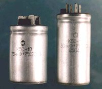 The loss of performance of capacitors may occur due to:
i) a short circuit inside it;
b) a chain break inside it;
c) increase in leakage current;
d) decrease in capacity.
An inoperative capacitor can be determined by an ohmmeter, a special device for measuring capacitance, or a test circuit.
For a rough check of the suitability of capacitors, it is recommended to control them using resistance meters (ohmmeter, combined device - multimeter).
The verification procedure is as follows ...
How to determine the malfunction of thyristors
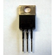 Loss of thyristor performance may occur due toand:
a) open circuit inside the device (combustion);
b) loss of controllability (combustion of the control electrode circuit);
c) loss of locking ability in the forward or reverse direction (breakdown);
d) breakage of conclusions.
An inoperative thyristor can be detected using an AC voltmeter, an ohmmeter, or a test circuit.
An inoperative thyristor in a circuit under AC voltage can generally be determined using ...
One-wire power transmission - fiction or reality?
 In 1892 in London, and a year later in Philadelphia, a famous inventor, a Serb by nationality, Nikola Tesla demonstrated the transmission of electricity through a single wire.
How he did this remains a mystery. Some of his records have not yet been decrypted, another part has burned down.
The sensationalism of Tesla's experiments is obvious to any electrician: after all, for the current to go through the wires, they must be a closed loop. And then suddenly - one ungrounded wire!
But, I think, modern electricians will have to be even more surprised when they find out that a person works in our country who also found a way to transfer electricity through one open wire ...