How to make an electronic match
 They say that you won’t save much on matches, and yet ... A simple and practical electronic match, the description of which I propose, will save you from the need to constantly monitor so that the matchboxes do not remain empty.
The “match” acts as follows. Electricity accumulated by the capacitor from the 220 V network is converted into a spark, from which gas ignites in the burner of the stove. The charge time to the amplitude value of the mains voltage is 2 - 3 s, and for its discharge only 0.1 s is sufficient.
Structurally, the “match” is made in the form of a cylinder consisting of two halves. Radioelements are located inside one, the other protects the ends of the arrester from accidental short circuit, otherwise the “match” included in the network immediately disables the diode ...
Triacs: From Simple to Complex
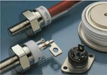 In 1963, a large family of Trinistors appeared another "relative" - triac. How does he differ from his "brothers" - trinistors (thyristors)? Remember the properties of these devices. Their work is often compared with the action of an ordinary door: the device is locked - there is no current in the circuit (the door is closed - there is no passage), the device is open - an electric current appears in the circuit (the door opened - enter). But they have a common flaw. Thyristors pass current only in the forward direction - this way an ordinary door easily opens "from itself", but no matter how much you pull it towards you - in the opposite direction, all efforts will be futile.
By increasing the number of semiconductor layers of the thyristor from four to five and equipping it with a control electrode, scientists found that a device with such a structure (later called a triac) is capable of passing electric current in both forward and reverse directions ...
Homemade soldering iron power supply
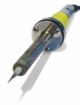 Everyone knows that working with a low-voltage electric soldering iron is safe and convenient. In production and in educational laboratories, low-voltage small-sized soldering irons have long been used everywhere, but in everyday life we most often have to be content with dangerous and bulky tools that operate on 220 V mains. make low voltage soldering iron power supply it’s not difficult for yourself.
The power supply is the simplest capacitive AC load limiter.
In the first, desktop version, the device is made in a light metal case, has two switches and one control indicator of the mains voltage, signaling about three switching modes.
Author schemes deliberately did not provide for the design of the block of devices for solder and flux, since these sets usually take up relatively much space. Therefore, the unit has only a curly stand for a soldering iron, which, when carried, can be removed inside and does not protrude beyond the dimensions of the unit ...
How to make a simple current regulator for a welding transformer
 An important design feature of any welding machine is the ability to adjust the operating current. In industrial apparatuses, different methods of adjusting the current are used: shunting with various types of chokes, changing the magnetic flux due to the mobility of the windings or magnetic shunting, using active ballast resistances and rheostats. The disadvantages of this adjustment include the complexity of the design, the bulkiness of the resistances, their strong heating during operation, inconvenience when switching.
The most optimal option is to make it with taps while winding the secondary winding and, changing the number of turns, change the current. However, this method can be used to adjust the current, but not to adjust it over a wide range.In addition, the regulation of the current in the secondary circuit of the welding transformer is associated with certain problems.
So, significant currents pass through the control device, which leads to its cumbersomeness, and for the secondary circuit it is almost impossible to choose such powerful standard switches that they can withstand currents up to 200 A. Another thing is the primary winding circuit ...
Modding a computer with a beautifully illuminated analog voltmeter
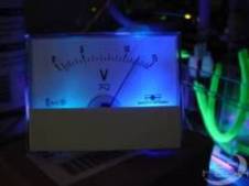 How to connect an analog voltmeter to a computer and highlight it.
Nowadays, high technology can often be found voltmeters / ammeters made in the form of an LCD indicator. But all this does not look as effective as an analog retro - a voltmeter flaunting on the front panel of your case! This article provides an overview and technical performance of mods in retro style.
The voltmeter is made in a traditional style and can work well with some cases. At radio bases, one can often see not only voltmeters, but also ammeters, which can also take place on the 5’25 plug. This voltmeter is capable of measuring DC voltage from 0 to 15 volts. This is what we need, because we will use a voltmeter as a 12 volt monitoring. Let's take a closer look. The lower part of the voltmeter is covered with a plastic cap. This technical maneuver is only for us - we can place a backlight under this cap ...
Fundamentals of Electrical Engineering for Computer Modding Lovers
 This article is for guidance only. The author is not responsible for any damage caused to the reader after reading it.
To begin with, everything in our computer works only because voltage, current is supplied to it :). Because of this, a number of processes and mechanisms are occurring, but we will not go deep. Where does this tension come from? Of course, from the Power Supply Unit (PSU). Its power is expressed in watts (watts).
Typically, power supplies go at least 250W, now they are increasingly installing a 300-350W power supply. Depends on its power, how many devices can be connected to your PC. In addition, there is such an indicator as the current strength in the circuit. But, as a rule, even in low-power PSUs there is a rather large current strength and this issue should not bother you. Also, power supplies can be of 2 types: AT or ATX. AT was used on older systems; ATX now dominates. Well, let's get down to electrical work ...
The most common schemes for switching on single-phase and three-phase electric meters
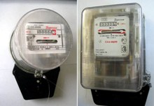 In this article we will consider the basic schemes for switching on single-phase and three-phase electric meters. I want to note right away that the switching circuits of induction and electronic electric meters are absolutely identical.
The mounting holes for fixing both types of electric meters should also be exactly the same, however, some manufacturers do not always adhere to this requirement, therefore, sometimes there may be problems installing an electronic electric meter instead of induction in terms of mounting on the panel.
The clamps of the current windings of electric meters are indicated by the letters G (generator) and N (load). In this case, the generator clamp corresponds to the beginning of the winding, and the load clip corresponds to its end.
When connecting the meter, it is necessary to ensure that the current through the current windings passes from their beginnings to the ends. To do this, the wires from the power supply side must be connected to the generator terminals (terminals G) of the windings, and the wires extending from the counter to the load side must be connected to the load terminals (terminals H) ...
Tricky probe instead of a tester
 I borrowed this sampler circuit from N. Shyla (Ukraine) in 1984. I don’t know who its author is, but many years of experience using this sampler show that it would be useful to share experience.
In my specialty, I deal with electric drives, as well as control circuits for automatic lines, etc. I believe that in nine out of ten cases this probe replaces a regular tester. The probe allows you to evaluate the magnitude and sign ("+", "-", "~") of the voltage in several ranges: up to 36 V,> 36 V,> 110 V,> 220 V, 380 V, as well as ringing electric circuits, such as the contacts of relays, starters, their coils, incandescent lamps, p-n transitions, LEDs, etc., i.e. almost everything that an electrician encounters in the course of his work (with the exception of measuring current).
In the diagram, the switches SA1 and SA2 are shown in a non-pressed state, i.e. in the position of the voltmeter. The magnitude of the voltage can be judged by the number of LEDs in the line VD3 ... VD6, VD1 and VD2 indicate the polarity. Resistor R2 must be made of two or three identical resistors connected in series with a total resistance of 27 ... 30 kOhm. The pressed switch SA2 turns the probe into a classic dial, i.e. battery plus a light bulb. If you press both switches SA1 and SA2, then you can check the circuit in two resistance ranges: - the first range is from 1 MOhm and above to ~ 1.5 kOhm (VD15 is on); - second range - from 1 kOhm to 0 (VD15 and VD16 are lit) ...
