Categories: Practical Electronics, Repair of household appliances
Number of views: 39681
Comments on the article: 1
How to use the oscilloscope
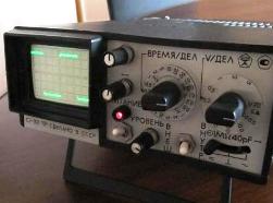 In the article “Electronic oscilloscope - device, principle of operation” this universal appliance was briefly described. The information given is sufficient to make the measurement process conscious, but in the case of repair of such a complex device, deeper knowledge will be needed, because the circuitry of electronic oscilloscopes is very diverse and quite complicated.
Most often, a beginner radio amateur has at his disposal a single-beam oscilloscope, but having mastered the methods of using such an instrument, it will not be difficult to switch to a two-beam or digital oscilloscope.
Figure 1 shows a fairly simple and reliable C1-101 oscilloscope with so few handles that it is absolutely impossible to get confused. Please note that this is not some kind of oscilloscope for school physics lessons, it was just that that was used in production only twenty years ago.
Oscilloscope power not only 220V. It can be powered from a 12V DC source, such as a car battery, which allows you to use the device in the field.
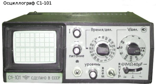
Figure 1. Oscilloscope C1-101
Auxiliary adjustments
On the upper panel of the oscilloscope are knobs for adjusting the brightness and focusing of the beam. Their purpose is clear without explanation. On the front panel are all other controls.
Two knobs, indicated by arrows, allow you to adjust the beam position vertically and horizontally. This allows you to more accurately combine the image of the signal on the screen with the grid to improve the reading of the divisions.
The zero voltage level is located on the center line of the vertical scale, which allows you to observe a bipolar signal without a constant component.
To study a unipolar signal, for example, digital circuits, it is better to move the beam to the lower division of the scale: you will get one vertical scale of six divisions.
On the front panel there are also a power switch and a power indicator.
Signal gain
The “V / div” switch sets the sensitivity of the vertical deflection channel. The channel Y gain is calibrated, it changes in increments of 1, 2, 5, there is no smooth adjustment of sensitivity.
Rotation of this switch should ensure that the amplitude of the pulse under study is at least 1 division of the vertical scale. Only then can stable signal synchronization be achieved. In general, you should strive to get the signal span as large as possible, until it goes beyond the grid. In this case, the accuracy of the measurements increases.
In general, the recommendation for choosing the gain can be this: unscrew the switch counterclockwise to the 5V / div position, and then rotate the knob clockwise until the signal amplitude on the screen becomes as recommended in the previous paragraph. What is it like in the case of a multimeter: if the magnitude of the measured voltage is unknown, start the measurement from the highest voltage range.
The most recent clockwise position of the sensitivity switch in the vertical direction is indicated by a black triangle with the inscription "5DEL". In this position, rectangular pulses with a span of 5 divisions appear on the screen, the pulse frequency is 1 KHz. The purpose of these pulses is to check and calibrate the oscilloscope. In connection with these impulses, a somewhat comical case is recalled, which can be told as a joke.
Once, a friend came to our workshop and asked to use an oscilloscope to establish some kind of self-made structure.After several days of creative torment, we hear from him such an exclamation: “Oh, you turned off the power, but what impulses are so good!” It turned out that out of ignorance, he simply turned on the calibration pulses, which are not controlled by any knobs on the front panel.
Open and closed entrance
Directly below the sensitivity switch is a three-position switch of operating modes, which are often called “open input” and “closed”. In the extreme left position of this switch, it is possible to measure direct and alternating voltages with a constant component.
In the right position, the input of the vertical deviation amplifier is turned on through the capacitor, which does not pass the constant component, but you can see the variable, even if the constant component is far from 0V.
As an example of using a closed input, one can cite such a widespread practical problem as measuring the ripple of a power source: the output voltage of the source is 24V, and the ripple should not exceed 0.25V.
If we assume that the voltage is 24V when the sensitivity of the vertical deviation channel is 5V / div. occupying almost five divisions of the scale (zero will have to be set on the lowest line of the vertical scale), the beam will fly up to the very top, and pulsations in tenths of a volt will be almost invisible.
To accurately measure these pulsations, it is enough to put the oscilloscope in closed input mode, place the beam in the center of the vertical scale and select a sensitivity of 0.05 or 0.1 V / div. In this mode, the ripple measurement will be quite accurate. It should be noted that the constant component can be quite large: the closed input is designed to operate with a constant voltage of up to 300V.
In the middle position of the switch, the measuring probe is simply DISCONNECTED from the input of amplifier Y, which makes it possible to set the position of the beam without disconnecting the probe from the signal source.
In some situations, this property is quite useful. The most interesting thing is that this position is indicated on the oscilloscope panel by the icon of a common wire, earth. It seems that the probe is connected to a common wire. And then what will happen?
On some oscilloscope models, the input mode switch does not have a third position, it's just a button or a toggle switch that switches between open / closed input modes. It is important that in any case there is such a switch.
To preliminarily evaluate the performance of the oscilloscope, just touch the signal (sometimes hot) end of the probe with your finger: a network tip in the form of a blurry beam should appear on the screen. If the sweep frequency is close to the network frequency, a blurry, torn, and shaggy sine wave will appear. When the finger touches the “earthen” end of the pickups on the screen, of course, there will be no.
Here you can recall one of the ways to check capacitors for a break: if you take a serviceable capacitor in your hand and touch it with the hot end, the same shaggy sinusoid appears on the screen. If the capacitor is open, then no changes will occur on the screen.
Sweep Management
Switch "Time / div." set the duration of the sweep. When observing a periodic signal by rotating this switch, it is necessary to ensure that one or two signal periods are displayed on the screen.
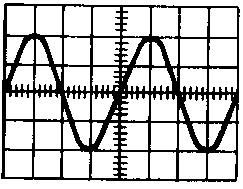
Figure 2
The sweep synchronization knob C1-101 is indicated by just one word, “Level”. In addition to this pen, the C1-73 oscilloscope has a “stability” knob (some feature of the sweep circuit), for some oscilloscopes the same pen is simply called “SYNCHR”. The use of this pen should be described in more detail.
How to achieve a stable signal image
When connected to the circuit under study, the screen most often may display the picture shown in Figure 3.
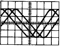
Figure 3
In order to get a stable image, turn the “Sync.” Knob, which is labeled “Level” on the front panel of the C1-101 oscilloscope. On various oscilloscopes, for some reason, different designations of control elements are found, but in fact it is the same pen.
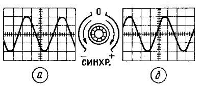
Figure 4. Image synchronization
To get a stable signal from the blurry image shown in Figure 19, just turn the “SYNCHR.” Knob or in our case "level". When rotating counterclockwise to the minus sign, a signal image will appear on the screen, in this case a sinusoid, shown in Figure 20a. Synchronization begins on the falling edge of the signal.
When you turn the same knob to the plus sign, the same sine wave will look like in Figure 4b: the scan starts on an ascending edge. The first sine wave period starts just above the zero line, this affects the sweep start time.
If the oscilloscope has a delay line, then there will be no such loss. For a sinusoid, this may not be particularly noticeable, but when studying a rectangular pulse, you can lose the entire front of the pulse in the image, which in some cases is quite important. Especially when working with external scan.
Working with External Scan
Next to the "LEVEL" control is a toggle switch, designated as "EXT / IN". In the “VNUTR” position, the sweep starts from the signal under investigation. It is enough to apply the signal under test to input Y and turn the “LEVEL” knob until a stable image appears on the screen, as shown in Figure 4.
If the said toggle switch is set to the position “OUT”, then a stable image cannot be obtained by any rotation of the “LEVEL” knob. To do this, you need to send a signal through which the image will be synchronized to the external synchronization input. This entrance is located on a white plastic panel located to the right of entrance Y.
The ramp voltage output jacks (used to control various GKCh), the calibration voltage output (can be used as a pulse generator) and the common wire socket are also located there.
As an example, where it may be necessary to work with an external scan, the pulse delay circuit shown in Figure 5 can serve.
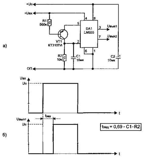
Figure 5. Pulse delay circuit on timer 555
When a positive pulse is applied to the input of the device, the output pulse appears with a delay determined by the parameters of the RC chain, the delay time is determined by the formula shown in the figure. But according to the formula, the value is determined very approximately.
In the presence of a two-beam oscilloscope, it is very easy to determine the time: it is enough to apply both signals to different inputs and measure the pulse delay time. And if there is no double beam oscilloscope? This is where the external scan mode comes to the rescue.
The first thing to do is to apply the input signal of the circuit (Fig. 5) to the external synchronization input and connect the input Y here. Then, turn the LEVEL knob to achieve a stable image of the input pulse, as shown in Figure 5b. In this case, two conditions must be met: the VNESH / VNUTR toggle switch is set to the VNESh position, and the signal under investigation must be in operation. periodic, and not single, as shown in Fig. 5.
After that, you need to remember the position on the screen of the input signal and apply the output signal to input Y. It remains only to calculate the required delay on the divisions of the scale. Naturally, this is not the only circuit where it may be necessary to determine the delay time between two pulses; there are a great many of such circuits.
The next article will talk about the types of signals under study and their parameters, as well as how to make various measurements using an oscilloscope.
Continuation of the article: Taking an Oscilloscope Measurement
Boris Aladyshkin
See also at bgv.electricianexp.com
:
