Categories: Featured Articles » Practical Electronics
Number of views: 149,726
Comments on the article: 13

How to determine unknown transformer parameters
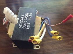
 

How to determine unknown transformer parametersThe first thing to do is to take a piece of paper, a pencil and a multimeter. Using all this, ring the transformer windings and draw a diagram on paper. This should result in something very similar to Figure 1.

The conclusions of the windings in the picture should be numbered. It is possible that the conclusions will be much smaller, in the simplest case there are only four: two terminals of the primary (network) winding and two terminals of the secondary. But this does not always happen, more often there are several more windings.

Some conclusions, although they exist, may not “ring” with anything. Are these windings torn off? Not at all, most likely these are shielding windings located between other windings. These ends are usually connected to a common wire - the "ground" of the circuit.

Therefore, it is desirable to record the winding resistances on the obtained circuit, since the main goal of the study is to determine the network winding. Its resistance, as a rule, is greater than that of other windings, tens and hundreds of ohms. Moreover, the smaller the transformer, the greater the resistance of the primary winding: the small diameter of the wire and a large number of turns affect. The resistance of the lowering secondary windings is almost zero - a small number of turns and a thick wire.

About how to correctly measure the resistance with a multimeter, see here:How to measure voltage, current, resistance with a multimeter, check diodes and transistors
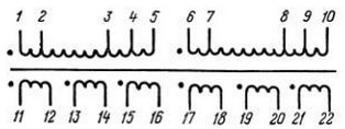
Transformer winding circuit

Fig. 1. Scheme of transformer windings (example)

Suppose that we managed to find the winding with the highest resistance, and we can consider it network. But you do not need to immediately include it in the network. In order to avoid explosions and other unpleasant consequences, it is best to make a test switch-on by turning on a series of coils with a winding, a 220V bulb with a power of 60 ... 100W, which will limit the current through the winding to 0.27 ... 0.45A.

The power of the bulb should approximately correspond to the overall power of the transformer. If the winding is determined correctly, then the bulb does not light, in extreme cases, the filament glows a little. In this case, you can almost safely include the winding into the network, for starters it is better to use a fuse for a current of no more than 1 ... 2A.

If the light bulb burns quite brightly, then it may turn out to be a winding of 110 ... 127V. In this case, you should ring the transformer again and find the second half of the winding. After that, connect the halves of the windings in series and re-enable. If the light goes out, then the windings are connected correctly. Otherwise, interchange the ends of one of the found half-windings.

So, we assume that the primary winding is found, the transformer was able to be connected to the network. The next thing that needs to be done is to measure the idling current of the primary winding. For a working transformer, it amounts to no more than 10 ... 15% of the rated current under load. So for a transformer, the data of which are shown in Figure 2, when powered from a 220V network, the open-circuit current should be within 0.07 ... 0.1A, i.e. no more than a hundred milliamps.
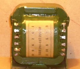
Transformer TPP-281

Fig. 2. Transformer TPP-281


How to measure transformer idle current

Idling current should be measured with an alternating current ammeter. In this case, at the time of inclusion in the network, the terminals of the ammeter must be short-circuited, since the current when the transformer is turned on can be a hundred or more times the nominal. Otherwise, the ammeter may simply burn out. Next, open the conclusions of the ammeter and look at the result. In this test, let the transformer run for about 15 ... 30 minutes and make sure that no noticeable heating of the winding occurs.


The next step is to measure the voltage on the secondary windings without load, - the open circuit voltage.Suppose that a transformer has two secondary windings, and each voltage is 24V. Almost what you need for the above amplifier. Next, we check the load capacity of each winding.

For this, it is necessary to connect a load to each winding, in the ideal case a laboratory rheostat, and by changing its resistance, ensure that the voltage across the winding drops by 10-15 %%. This can be considered the optimal load for this winding.

Together with voltage measurement, current is measured. If the indicated voltage drop occurs at a current, for example 1A, then this is the rated current for the tested winding. Measurements should be started by setting the rheostat engine R1 to the right position according to the diagram.
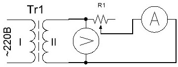
Transformer Secondary Test Scheme

Figure 3. Test transformer secondary circuit

Instead of a rheostat, light bulbs or a piece of spiral from an electric stove can be used as a load. Measurements should be started with a long piece of spiral or with the connection of a single bulb. To increase the load, you can gradually shorten the spiral by touching it with a wire at different points, or by increasing the number of connected lamps one at a time.

To power the amplifier, one winding with a midpoint is required (see article "Transformers for UMZCH") We connect two secondary windings in series and measure the voltage. It should be 48V, the connection point of the windings will be the midpoint. If the voltage at the ends of the windings connected in series is equal to zero, then the ends of one of the windings should be interchanged.

In this example, everything turned out almost successfully. But more often it happens that the transformer has to be rewound, leaving only the primary winding, which is almost half the battle. How to calculate a transformer is the topic of another article, it was only told about how to determine the parameters of an unknown transformer.

Boris Aladyshkin

See also at bgv.electricianexp.com:

  • How to determine the number of turns of transformer windings
  • How to make a do-it-yourself indicator of connecting electrical appliances to a 220V network
  • Transformers and autotransformers - what is the difference and feature
  • How to find out the power and current of a transformer by its appearance
  • Home-made step-down transformer for damp rooms

  •  
     
    Comments:

    # 1 wrote: | [quote]


    Why close the ammeter before turning on the primary winding? Inductance will not allow inrush current (unlike capacitance).

     
    Comments:

    # 2 wrote: | [quote]


    The article is good and necessary. Indeed, in the economy of craftsmen there are many diverse transformers and chokes with unknown parameters.
    However, I propose to correct the text of the article. The article is written somewhat impractical.
    1. It is unlikely that anyone at home has rheostats that the author recommends.
    2. The load of the windings is proposed to change the length of the spiral. Two dangerous factors: - current can greatly heat the spiral; - if the isolation of the tested winding from the connected to the network is incomplete, an electric shock is possible. It is necessary to stipulate in more detail.
    3. In the 7th paragraph of the text there is an unsuccessful text "If the light goes out ...". Better if you write that its brightness has decreased markedly.
    In general, B. Aladyshkin’s articles on the site are not only useful to read, but also pleasant. Good qualifications, considerable erudition and a broad outlook in published materials inspire confidence in the argumentation and technical reliability of the information presented by the author.

     
    Comments:

    # 3 wrote: | [quote]


    Quote: Vladimir
    Why close the ammeter before turning on the primary winding? Inductance will not allow inrush current (unlike capacitance)

    As you might suppose, more than one arrow in the tseshchiki "theorists" in my circle bent.
    Do not forget that a transformer is an inductance on iron (ferromagnetics) and there is such a thing as hysteresis and its consequence -launchercurrent.Moreover, its peak value depends on the phase of the voltage at the time of switching on and in the worst case (voltage phase 0) can be more than a hundred times the value of the open circuit current in the first period of the network. In practice, for a 9-amp LATR, the peak current during a “failed” turn-on can exceed 100A. Therefore, to exclude the regular death of the cachets during the measurement of Ixx, a device was made in the form of a socket and a pair of jacks for the cache, closed by a toggle switch. First, the toggle switch is put into the “closed” position, then the measured transformer is connected, then the mains voltage is turned on, and only then the toggle switch is opened and the open-circuit current is measured and further experiments :)

     
    Comments:

    # 4 wrote: | [quote]


    Sergei,
    Hysteresis, if it affects the inrush current, is only a loss factor, and a short-term inrush could be due to the load on the secondary windings of the transformer (capacitive or non-linear), or your wards simply messed up the windings. As for the "0 phase voltage", this is just the best case of connecting voltage to the load.

     
    Comments:

    # 5 wrote: | [quote]


    Everything is exactly as it is, as I have written. The wards did not confuse the windings (and I was there for what - I checked) :)
    Unfortunately, the full operation of the transformer (and other electrical machines) cannot be understood without a deep knowledge of electrical engineering, knowledge of the higher mathematics apparatus in terms of understanding and solving integral differential equations.

    Quote: Vladimir
    "0 phase voltage", then this is just the best case

    This is precisely the worst case - due to the fact that the current in the inductance phase lags behind the voltage, and at "0" voltage the current through the inductance is maximum.
    That's just to understand exactly this, you need to have a good understanding of higher mathematics or just believe that the square J gives -1 as a result (or that there is a root of minus one, which is not at all obvious.) :)

    But you can simply trust those who understand the issue. Do you trust doctors?

     
    Comments:

    # 6 wrote: Alexei | [quote]


    Comment No. 5 is about nothing. Purely just to show the coolness of the commenter. It was always surprising and a little annoying the desire of individual comrades (most often from among the teachers) to try to operate out of place and out of place to refer to logarithms, integrals, etc. things. And at the same time argue that everyone is simply obliged to understand these things. Yes, such a deep knowledge of mathematics in life is not necessary for most people. If you take the same electric cars. How many different scientific dregs involved in cool mathematics are contained in any textbook on electrical machines. Magnetic fields, electromagnetic processes, transients, etc. "Numerical calculation of electromechanical characteristics according to the T-shaped equivalent circuit taking into account the surface effect and saturation of the magnetic circuit." Well, and who needs it? The maximum is only for designers of electric machines, and I’m not sure, because all calculations are now probably automated and computerized. In 80% of cases, what is contained in textbooks is interesting only to the creators of these textbooks themselves. I would tell the whole course on electric cars in about ten hours. But these would be important things that are needed in real practice. And everything else is a simple theoreticization that is not needed by anyone, which clogs the head and does not bear absolutely no benefit.

     
    Comments:

    # 7 wrote: | [quote]


    To comment No. 6
    If you throw out from the textbooks “a simple theoretician that is not needed by anyone, which clogs his head and does not bear absolutely any benefit”, then this will be a manual for electric fitters.
    However, then the country with such textbooks will soon turn into a banana republic, where the most intelligent of people will explain the operation of the transformer as in a joke:
    "The question is how does the transformer work?
    The answer is MMMMMMMMMMMMMMMMMMMMMMM (mock hum) "

     
    Comments:

    # 8 wrote: | [quote]


    But isn’t it easier (and safer) by the second step, after dialing, not to shove the unknown body into the socket, but to apply 3 to 5 volts of change from any low-power unit to any secondary found (in case of emergency, open any existing transformer adapter), and calmly check voltage on all winding rings. The primary-secondary will be immediately visible, and the transformation ratio is not a problem to calculate ...

     
    Comments:

    # 9 wrote: MaksimovM | [quote]


    I think that the method for determining the parameters of a transformer, discussed in this article, is more suitable for the case when the type of transformer is unknown. If its type is indicated on the transformer, as in the example considered in the article, then it is easier to find a guide to transformers on the Internet, where all the necessary data will be indicated. Among which: the numbering of the terminals of all windings, their rated voltages and currents, the number of turns, as well as the type of wire of each of the windings.

     
    Comments:

    # 10 wrote: | [quote]


    True Dmitry, safer and more competent, but not always easier. It all depends on the current conditions.

    And about what is easier ..? Here's an example of a "famous" transformer:

    Power transformer 4 709 103 Made in the USSR. Price 3r. 50k 7 pins Ш-shaped core. External dimension: 52х62х32 mm. We begin to look for a directory, time has gone.

     
    Comments:

    # 11 wrote: MaksimovM | [quote]


    Gennady, I had in mind the common types of transformers, on the Internet there are reference books on TS, CCI, TAN, etc. You can try to find reference data on the transformer on the Internet, and if they are not, then go on to determine them empirically. After all, it is not always possible to correctly determine the nominal parameters of a transformer, according to the directory it will always be more accurate.

     
    Comments:

    # 12 wrote: Dmitriy | [quote]


    Suppose there is just Sh-shaped iron without windings. How to determine what power can be removed from it? Measure the dimensions with a ruler, yes. What are the references? which multimeter? about the size you can understand everything. and what to do? how to distinguish iron 700 watts from iron 1200 watts? won't fit in the window, yes

     
    Comments:

    # 13 wrote: Vitaliy | [quote]


    I need help on how to calculate the power of trance for iron, and how to make a 220 / 13.5volt voltage stabilizer yourself so that there is no voltage drawdown under load. I want to make bp for honey separator and electric knife at the same time. Honey extractor power 140vat and knife 60 watts. It’s hard to carry the battery at home, it’s only necessary in the field. Help solve the problem please.