Categories: Practical Electronics, Electrician Secrets, Electrician at home
Number of views: 55459
Comments on the article: 7
How to make a do-it-yourself indicator of connecting electrical appliances to a 220V network
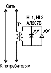
 Indication device allows you to monitor when leaving home: are electrical appliances disconnected from the network? If any load with a power> 8 W remains on, then both LEDs HL1 and HL2 light up (see figure). The brightness of the glow is small at a load of 8 watts (a dot in the LED is on), therefore, in bright light, to see the glow, you need to cover with your palm the penetration of bright light on the LED. LED (s) are installed at the front door. Conductors to them (0.2 mm) are laid under the wallpaper (due to the small current passing through them). LED HL2 can be excluded from the circuit, and if it remains, then HL1 can be installed on the inside of the door, and HL2 - on the outside.
As a T1 transformer, ready-made ones are used, which have a winding with a large number of turns (2000-3000, or maybe less) and it is possible to wind 8 to 10 turns of a mounting wire of sufficient cross-section. In each particular transformer, the number of turns is selected experimentally. These 8 - 10 turns will be the primary winding of the transformer, and the secondary - those that are in the finished transformer.
Different types of finished transformers have been tested. Suitable for this purpose TVK 70-L2. However, it should be noted that not all transformers work well in this circuit. The greater the load, the thicker it is necessary to take the mounting wire for the primary winding.
Extra windings can be removed from the transformer, then there will be more space for winding the mounting wire, as the primary winding of the T1 transformer.

The primary winding T1 is included in the gap of the wire supplying voltage to the apartment (for example, in the apartment box or in the power board). A necessary condition for the implementation of such a connection, so that the primary winding wire is of sufficient cross-section (it was heated under load).
See also at bgv.electricianexp.com
:
