Categories: Practical Electronics, All about LEDs
Number of views: 277765
Comments on the article: 18
How to connect the LED to the lighting network
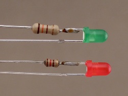 After reading this headline, someone might ask, “Why?” Yes, if you just stick Light-emitting diode even if it is plugged in according to a certain pattern, it does not have practical value, it will not bring any useful information. But if you connect the same LED in parallel with a heating element controlled by a temperature regulator, you can visually control the operation of the entire device. Sometimes this indication allows you to get rid of many small problems and troubles.
In the light of what has already been said about turning on the LEDs in previous articles, the task seems trivial: just set the limiting resistor of the desired value, and the issue is resolved. But all this is good, if you feed the LED with a rectified constant voltage: as they connected the LED in the forward direction, it remained.
When working on alternating voltage, everything is not so simple. The fact is that, in addition to the direct voltage, the LED will also be affected by the voltage of reverse polarity, because each half-cycle of the sinusoid changes its sign to the opposite. This reverse voltage will not illuminate the LED, but it can become unusable very quickly. Therefore, it is necessary to take measures to protect against this "harmful" voltage.
In the case of mains voltage, the calculation of the quenching resistor should be based on a voltage of 310V. Why? Everything is very simple here: 220V is current voltage, the amplitude value is 220 * 1.41 = 310V. The amplitude voltage at the root of two (1.41) times greater than the current, and this should not be forgotten. Here is the forward and reverse voltage applied to the LED. It is from the value of 310V that the resistance of the quenching resistor should be calculated, and it is from this voltage, only of reverse polarity, that the LED is protected.
How to protect the LED from reverse voltage
For almost all LEDs, the reverse voltage does not exceed 20V, because no one was going to make a high-voltage rectifier on them. How to get rid of such misfortune, how to protect the LED from this reverse voltage?
It turns out that everything is very simple. The first way is to turn on the regular one with the LED rectifier diode with high reverse voltage (not lower than 400V), for example, 1N4007 - reverse voltage 1000V, forward current 1A. It is he who will not miss the high voltage of negative polarity to the LED. The scheme of such protection is shown in Fig.1a.
The second method, no less effective, is simply to shunt the LED with another diode, turned on counter-parallel, Fig. 1b. With this method, the protective diode does not even have to be with a high reverse voltage, any low-power diode, for example, KD521, is sufficient.
Moreover, you can simply turn on the opposite - in parallel, two LEDs: opening one by one, they themselves will protect each other, and even both will emit light, as shown in Figure 1c. This is already the third method of protection. All three protection schemes are shown in Figure 1.
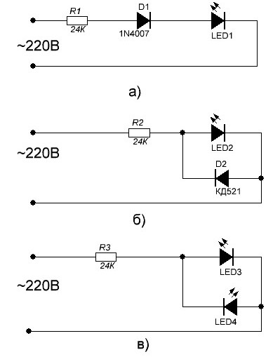
Figure 1. Circuit protection LEDs against reverse voltage
The limiting resistor in these circuits has a resistance of 24KΩ, which, with an operating voltage of 220V, provides a current of the order of 220/24 = 9.16mA, can be rounded to 9. Then, the power of the quenching resistor will be 9 * 9 * 24 = 1944mW, almost two watts. This despite the fact that the current through the LED is limited to 9mA. But prolonged use of the resistor at maximum power will not lead to anything good: first it will turn black and then completely burn out. To avoid this, it is recommended to put in series two resistors of 12Kohm with a power of 2W each.
If you set the current level to 20mA, then power resistor will be even more - 20 * 20 * 12 = 4800mW, almost 5W! Naturally, no one can afford a stove of such power for space heating. This is based on one LED, but what if there is a whole LED garland?
Capacitor - Wattless Resistance
The circuit shown in Figure 1a, the protective diode D1 “cuts off” the negative half-cycle of the alternating voltage, therefore the power of the quenching resistor is halved. But, all the same, the power remains very significant. Therefore, often as a limiting resistor ballast capacitor: he will limit the current no worse than a resistor, but he will not give off heat. After all, it is not for nothing that a capacitor is often called a free resistance. This switching method is shown in Figure 2.
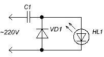
Figure 2. Diagram for turning on the LED through the ballast capacitor
Everything seems to be fine here, even there is a protective diode VD1. But two details are not provided. Firstly, the capacitor C1 after turning off the circuit can remain in a charged state and store the charge until someone discharges it with their own hand. And this, believe me, is sure to someday happen. The electric shock is, of course, not fatal, but rather sensitive, unexpected and unpleasant.
Therefore, in order to avoid such a nuisance, these quenching capacitors are shunted by a resistor with a resistance of 200 ... 1000K. The same protection is installed in transformerless power supplies with a quenching capacitor, in optocouplers and some other circuits. In Figure 3, this resistor is designated as R1.
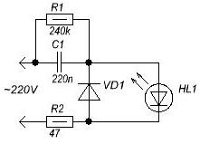
Figure 3. Connection diagram of the LED to the lighting network
In addition to the resistor R1, the resistor R2 also appears on the circuit. Its purpose is to limit the inrush of the current through the capacitor when voltage is applied, which helps protect not only the diodes, but the capacitor itself. It is known from practice that in the absence of such a resistor, the capacitor sometimes breaks, its capacity becomes much less than the nominal. Needless to say, the capacitor must be ceramic for an operating voltage of at least 400V or special for operation in AC circuits for a voltage of 250V.
Another important role is assigned to the resistor R2: in the event of a breakdown of the capacitor, it operates as a fuse. Of course, the LEDs will also have to be replaced, but at least the connecting wires will remain intact. In fact, this is how a fuse works in any switching power supply, - the transistors burned out, and the circuit board remained almost untouched.
In the diagram shown in Figure 3, only one LED is shown, although in fact several of them can be switched on sequentially. The protective diode will completely cope with its task alone, but the capacity of the ballast capacitor will have to be calculated, at least approximately, but still.
How to calculate the capacity of a quenching capacitor
In order to calculate the resistance of the quenching resistor, it is necessary to subtract the voltage drop on the LED from the supply voltage. If several LEDs are connected in series, then simply add up their voltages, and also subtract from the supply voltage. Knowing this residual voltage and the required current, according to Ohm's law, it is very simple to calculate the resistance of a resistor: R = (U-Uд) / I * 0.75.
Here U is the supply voltage, Ud is the voltage drop across the LEDs (if the LEDs are connected in series, then Ud is the sum of the voltage drops across all the LEDs), I is the current through the LEDs, R is the resistance of the quenching resistor. Here, as always, is the voltage in Volts, the current in Amperes, the result in Ohms, 0.75 is a coefficient for increasing reliability. This formula has already been given in the article. "On the use of LEDs".
The magnitude of the direct voltage drop for LEDs of different colors is different. At a current of 20 mA, the red LEDs are 1.6 ... 2.03V, yellow 2.1 ... 2.2V, green 2.2 ... 3.5V, blue 2.5 ... 3.7V. White LEDs have the highest voltage drop, having a wide emission spectrum of 3.0 ... 3.7V.It is easy to see that the scatter of this parameter is wide enough.
Here are the voltage drops of just a few types of LEDs, just by color. In fact, there are much more of these colors, and the exact value can be found only in the technical documentation for a specific LED. But often this is not required: in order to get a result acceptable for practice, it is enough to substitute some average value (usually 2V) in the formula, of course, if this is not a garland of hundreds of LEDs.
To calculate the capacity of a quenching capacitor, the empirical formula C = (4.45 * I) / (U-Uд) is applied
where C is the capacitance of the capacitor in microfarads, I is the current in milliamperes, U is the amplitude network voltage in volts. When using a chain of three series-connected white LEDs, Ud is approximately about 12V, U is the amplitude of the mains voltage of 310V, a capacitor with a capacity of 20mA is needed to limit the current
C = (4.45 * I) / (U-Uд) = C = (4.45 * 20) / (310-12) = 0.29865 μF, almost 0.3 μF.
The closest standard capacitor value is 0.15 μF, therefore, for use in this circuit, two parallel-connected capacitors will have to be used. Here it is necessary to make a remark: the formula is valid only for an alternating voltage frequency of 50 Hz. For other frequencies, the results will be incorrect.
The capacitor must first be checked
Before using a capacitor, it must be checked. For starters, just plug in 220V, it is better through a fuse 3 ... 5A, and after 15 minutes check for touch, but is there noticeable heating? If the capacitor is cold, then you can use it. Otherwise, be sure to take another, and also pre-check. After all, all the same, 220V is no longer 12, here everything is somewhat different!
If this test was successful, the capacitor did not heat up, then you can check if there was an error in the calculations, whether the capacitor is of the same capacity. To do this, you need to turn on the capacitor as in the previous case in the network, only through an ammeter. Naturally, the ammeter should be AC.
This is a reminder that not all modern digital multimeters can measure alternating current: simple, cheap devices, for example, very popular with radio amateurs DT838 Seriesare able to measure only direct current, which such an ammeter will show when measuring AC current no one knows. Most likely it will be the price of firewood or the temperature on the moon, but not the alternating current through the capacitor.
If the measured current is approximately the same as it turned out in the calculation according to the formula, then you can safely connect the LEDs. If instead of the expected 20 ... 30 mA it turned out 2 ... 3A, then here, either an error in the calculations, or the capacitor marking is incorrectly read.
Illuminated Switches
Here you can focus on another way to turn on the LED in the lighting network used in backlit switches. If such a switch is disassembled, then you can find that there are no protective diodes there. So, all that is written a little higher is nonsense? Not at all, you just have to carefully look at the disassembled switch, more precisely the resistor value. As a rule, its face value is not less than 200K, maybe even a little more. At the same time, it is obvious that the current through the LED will be limited to about 1 mA. A backlit circuit diagram is shown in Figure 4.
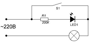
Figure 4. LED connection diagram in a backlit switch
Here, with one resistor, several "birds with one stone" are killed at once. Of course, the current through the LED will be small, it will glow weakly, but quite brightly to see this glow on a dark night in the room. But in the afternoon this glow is not necessary at all! So let yourself shine imperceptibly.
In this case, the reverse current will be weak, so weak that in no way can the LED burn. Hence the savings on exactly one protective diode, which was described above. With the release of millions, or maybe even billions, of circuit breakers per year, the savings are considerable.
It would seem that after reading the articles on LEDs, all questions about their application are clear and understandable. But there are still many subtleties and nuances when including LEDs in various circuits. For example, parallel and serial connection or, in another way, good and bad circuits.
Sometimes you want to collect a garland of several dozen LEDs, but how to calculate it? How many LEDs can be connected in series if there is a power supply unit with a voltage of 12 or 24V? These and other issues will be considered in the next article, which we will call “Good and bad LED switching circuits”.
Boris Aladyshkin
See also at bgv.electricianexp.com
:
