Categories: Practical Electronics, All about LEDs
Number of views: 32269
Comments on the article: 0
About using LEDs, LED device, how to light an LED
 Everyone is familiar with LEDs now: LED lights, LED lamps, ribbons, and much more. Thanks to the efforts of the developers, absolutely exotic devices appeared, for example, a nozzle on a water tap.
Outwardly, it is a transparent plastic cylinder: cool water poured in - inside the nozzle a blue LED lights up, it became warmer - it turned yellow, and even if the water is too hot, the nozzle turns red. The content of the internal filling is unknown, but the fact that LEDs are used as emitting elements is obvious.
The first LED was developed at the University of Illinois back in 1962. In 1990, bright, and later superbright LEDs were born.
The LED itself is very similar to a conventional rectifier diode, only when a direct current passes through it, the semiconductor crystal begins to glow. The English name of the LEDs is light emitting diode, or LED, which literally can be translated as a light emitting diode.
To obtain different wavelengths of radiation (color), various dopants are added to the semiconductor. The addition of aluminum, helium, indium, phosphorus causes the crystal to emit colors from red to yellow. To get a glow from blue to green, the crystals are doped with particles of nitrogen, gallium or indium.
Nowadays, white LEDs are probably the most common. Basically, these are products for creating lighting - from flashlights, souvenirs to serious spotlights for installation on roofs and facades of buildings. But here's an interesting detail: in nature, there is no semiconductor material that can glow in white.
How to be here? Ultraviolet radiation helped to get out of this situation: the "ultraviolet" crystal is covered with a layer of phosphor, approximately the same as it was done in fluorescent lamps, as a result of which the LED glows white.
But there is also some ambush. As in fluorescent lamps, the phosphor loses its properties over time, the glow becomes weak. However, in order for such wear to occur, the LED must continuously shine for at least a year, and maybe even more. So with periodic switching on and off, the service life of these devices is quite large.
Initially, the LEDs were intended mainly for indicating devices, they replaced the miniature incandescent lamps. The benefits here are undeniable. This is a low power consumption, low supply voltage, and also high durability: an incandescent lamp has a service life of no more than a thousand hours, while for LEDs this parameter amounts to several tens of thousands.
Some sources claim that the LED can operate continuously up to 11 years! But in some devices, in order to replace a light bulb, one has to resort to significant disassembly of the housing and the entire display panel. Here a hammer, a chisel and some other mother help in full.
A distinctive parameter of LEDs is a variety of colors, which allows you to do without the use of light filters. Compared to incandescent lamps LED bulbs possess increased mechanical strength, which makes it easy to tolerate vibration and shock loads. Within reasonable limits, of course.
LED device
The first LEDs were produced in metal cases with a transparent window. As technology improved, the hull began to be made entirely of plastic.The color of the plastic, as a rule, corresponds to the color of the glow, but transparent cases are also very common. What color such LED shines, can be found out only after its inclusion.
As well as conventional rectifier diodeThe LED has two pins anode and cathode. Therefore, when connecting, observe the polarity. The output of the anode, as a rule, is slightly longer than the cathode, but this is still a new LED. If the legs are already trimmed, then the conclusions can be determined by the "proverbial" multimeter: with the correct polarity of the connection, the LED lights up a little.
In the opposite direction, the device should show a large resistance, almost an open, as is the case with a conventional rectifier diode. The internal arrangement of the LED in a transparent housing is shown in Figure 1.

Figure 1. The internal structure of the LED in a transparent case
How to light an LED
Quite often, amateur radio amateurs ask the question: "What voltage is needed to light an LED?" Here you can see the analogy with incandescent lamps. This lamp is for 220V, and this one is for 12. In the case of using an LED, it cannot be said that this LED is for 5V, and this one is for 12V. The question is, why so?
The fact is that the LED is a current device: a current-limiting resistor is switched on in series with it, which is shown in Figure 2.

Figure 2 LED wiring diagram through a current-limiting resistor
It is easy to see that the LED is connected to a DC source with the correct polarity: the anode is connected to the positive pole of the battery, and the cathode through the limiting resistor, respectively, to the negative. Naturally, the limiting resistor can also be included in the rupture of the anode output, because the circuit is serial!
The DC source in the figure is shown as a galvanic cell with a voltage of not more than one and a half volts. In fact, it can be a battery of cells with a voltage of 12 ... 24V, and with the appropriate inclusion, even an alternating current lighting network of 220V. The main thing is to limit the direct current through the LED at the level stated in the technical documentation. For most modern LEDs, this current is 20mA.
But here it’s just right to make a small remark about the issue of LED voltage. The fact is that at present, for the purpose of miniaturization of electronic equipment, the production of LEDs with an integrated limiting resistor integrated in the housing has been established. This integration allows us to say that this LED has a working voltage of 12V, and this one is only 5.
It is with this marking that you can see the price tags on the shelves of radio markets. True, such devices are not common, therefore, one should not forget about the limiting resistor.
There is also a category of LEDs designed for a specific operating voltage. These are the so-called flashing LEDs containing an integrated generator inside, which makes the crystal blink at a given frequency. Attempts to change the blinking frequency with the help of external capacitors and other tricks are doomed to failure. Although some change in frequency can be achieved by varying the supply voltage.
So, flashing LEDs are produced for a specific voltage: high-voltage 3 ... 14V, and low-voltage 1.8 ... 5V. At the same time, the built-in limiting resistor for low-voltage flashing LEDs is absent. Here you need to show maximum attention. But back to ordinary LEDs.
So, it has already been said that the direct current of most LEDs is 20 milliamps. It is possible to make a little less (just the brightness will drop, and the color will be a little different than what was expected), but more is highly undesirable. It is this current value that is intended to provide the limiting resistor shown in Figure 2.
In order to calculate the resistance value of this resistor, you should know two parameters.Firstly, it is the supply voltage of the circuit (pay attention, it is SCHEMES, not a single LED) and, secondly, a direct voltage drop on the LED.
This direct drop is specified in the technical documentation, and for most types of LEDs it is in the range of 1.8 ... 3.6V (for each type its own, but most often 2V). This will be the direct voltage drop on the LED at a current of 20 mA. With such data, it is very simple to calculate the resistance of the limiting resistor. To make it clear where it comes from, you can use the simple diagram shown in Figure 3.

Figure 3LED connection diagram
It is obvious that the series-connected resistor R1 and LED HL1 are a voltage divider. It is also known that a direct voltage drop on the LED according to the reference data is exactly 2V. Here we have such a good LED.
Then, with a supply voltage of 12V, the voltage drop across the resistor R1 will be 12V - 2V = 10V. Hence, according to Ohm's law, it is easy to calculate the resistance of the resistor at which the current through the LED will be 20mA: R = U / I = 10V / 20mA = 0.5KΩ.
Formula for calculating the limiting resistor:
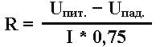
Everything is clear and simple here. In the numerator are the supply voltage and a direct voltage drop on the LED. The denominator contains the required current through the LED multiplied by a reliability factor of 0.75. In mechanics, this is called margin of safety.
In the case when several LEDs are connected in series, the voltage drop on them simply adds up and is substituted in the formula shown above. Naturally, in this case, the resistance R in this case becomes less than for a single LED.
Naturally, some power is released on the resistor. So that the resistor does not burn out immediately or over time, its power is usually calculated by the formula:
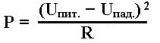
All quantities have the SI system dimension: voltage in volts, resistance in Ohms, power in watts.
Quite often there is a need for various ways of connecting LEDs, connecting them to various power sources, but this will be discussed in the continuation of the article.
See also: How to connect the LED strip to the power supply
Boris Aladyshkin
See also at bgv.electricianexp.com
: