Categories: Featured Articles » Practical Electronics
Number of views: 22519
Comments on the article: 0
Capacitors in electronic circuits. Part 2. Interstage communication, filters, generators
Beginning of the article: Capacitors in electronic circuits. Part 1
 The most common use of capacitors is the connection between individual transistor stages, as shown in Figure 1. In this case, the capacitors are called transient.
Transient capacitors pass the amplified signal and prevent the passage of direct current. When the power is turned on, the capacitor C2 is charged to the voltage at the collector of the transistor VT1, after which the passage of direct current becomes impossible. But the alternating current (amplified signal) makes the capacitor charge and discharge, i.e. passes through the capacitor to the next cascade.
Often in transistor circuitsat least the sound range, electrolytic capacitors are used as transients. The rated values of the capacitors are chosen so that the amplified signal passes without much attenuation.
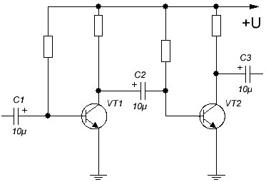
Picture 1.
Low pass and high pass filters
Sometimes it becomes necessary to skip some frequencies and weaken the passage of others. Such tasks are performed using filters that are created on the basis of RC circuits.
There are quite complex multi-link filters that even have their own names: Chebyshev, Bessel, Butterworth, and others. They all have their own distinctive features, characteristics, and, as a rule, several links. To compensate for losses, an active element is introduced into such filters - a transistor stage or an operational amplifier. Such filters are called active.
The simplest passive filters can be created from just two parts - resistor and capacitor. Figure 2 shows a diagram of a simple low-pass filter (low-pass filter). Such a filter freely passes low frequencies, and starting from the cutoff frequency, it slightly attenuates the output signal.
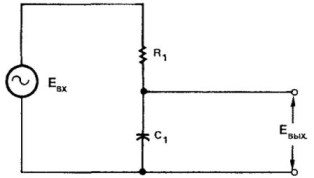
Figure 2. Low-pass filter circuit (LPF)
The simplest low-pass filter consists of only two parts - a resistor and a capacitor connected in series. The input signal from the generator is supplied to the serial RC circuit, and the output is removed from the capacitor C. At low frequencies, the capacitance of the capacitor is greater than the resistance of the resistor Xc = 1/2 * π * f * C, so a large voltage drop occurs on it.
With increasing frequency, the capacitance of the capacitor decreases, so the voltage drop or just the voltage on it becomes less. It is assumed that the generator is tuned to more than one frequency; its frequency varies. Such generators are called oscillating frequency generators or sweep generators. The frequency response of the simplest low-pass filter is shown in Figure 3.
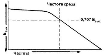
Figure 3. Frequency response of the low-pass filter
If in Figure 2 you swap the capacitor and resistor, you get a high-pass filter (HPF). Its circuit is shown in Figure 4. The main task of the high-pass filter is to weaken the frequencies below the cutoff frequency and skip the frequencies above.
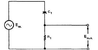
Figure 4. High-pass filter (HPF) circuit
In this case, the input signal is supplied to the capacitor, and the output is removed from the resistor. At low frequencies, the capacitance is large, so the voltage drop across the resistor is small.
For clarity and ease of perception (everything is known in comparison), you can mentally replace the capacitor with a resistor: instead of a capacitor, let it be 100K, and the output resistor 10K. It turns out just a voltage divider. Only in the case of a capacitor does this divider turn out to be frequency dependent. The frequency response of such a simple HPF is shown in Figure 5.
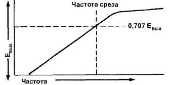
Figure 5. Frequency response of the HPF
At high frequencies, the capacitor resistance decreases, respectively, the voltage drop across the resistor, it also increases the output voltage of the HPF.
If you compare Figures 3 and 5, it is easy to see that the steepness of the decline in performance is not very steep. And what could be expected from such simplest schemes? But they have the right to life, and are used quite often in electronic circuits.
How to move the phase
You can look at any thing from different angles, and see it in a completely different light. So the RC circuits just examined can be applied not as frequency filters, but as phase-shifting elements. Here's what happens if an alternating current is applied to the circuit shown in Figure 6?

Figure 6
And this is what happens. The input voltage is supplied to the capacitor, the output is removed from the resistor. The input current through the capacitor is ahead of the input voltage. Therefore, the voltage drop across the resistor, and in general at the output of the phase-shifting circuit, is ahead of the input.
If the resistor and capacitor are interchanged, as shown in Figure 7, we get a circuit whose output voltage lags behind the input. Well, exactly the opposite, as in the previous scheme.

Figure 7
Such phase-shifting chains allow a small shift between the input and output signals, usually not more than 60 degrees. In cases where the shift is required on a large scale, the sequential inclusion of several chains is used.
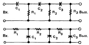
Figure 8. Phase shifting chains
Such inclusion of so many passive elements at once leads to a significant attenuation of the input signal. To restore the initial level, the use of amplification cascades is required.
In amateur radio practice, situations often arise when suddenly and suddenly a sine wave generator is needed, not even tunable, but simply on one frequency. Then a soldering iron, a few junk parts are picked up, and soon a sinusoid sounds melodiously in the room. Whoever hears knows what it is about.
Sine wave generator
You can collect everything on single transistor. In fact, the generator is an amplifier on a single transistor, covered by positive feedback using phase-shifting chains. And any positive feedback leads to the appearance of generation. And this case is no exception.
A sinusoidal signal is removed from the collector of the transistor, preferably through an isolation capacitor. It’s really good not to regret another transistor and shoot the output signal through an emitter follower.
Multisim single transistor generator
A schematic diagram of a virtual generator is shown in Figure 9.
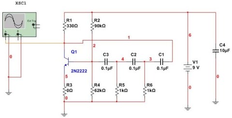
Figure 9. Diagram of a single-transistor generator in the Multisim program
Everything is clear and simple here: the generator itself with the battery and oscilloscope. Although you can add a comment to this simple scheme, suddenly, who will undertake to repeat it?
When you turn on the circuit does not start immediately. First, several empty sweeps take place on the oscilloscope, then a low voltage sine wave begins to appear, gradually increasing to several volts. The results of the study are shown in Figure 10.
Figure 10
A virtual circuit is, of course, good. But if someone decides to assemble this circuit in metal, well, at least on solderless breadboard, focus should be on tuning. Actually, the whole setup consists in the exact selection of the resistance of the resistor R2, which sets the operating point of the transistor.
To speed up the tuning process, you can temporarily connect a tuning resistor of 100 ... 200 kilograms instead. At the same time, do not forget to turn on the limiting resistor of approximately 10 ... 20K ohms in sequence.
As a transistor, a domestic KT315 or similar is quite suitable. Capacitors are any small-sized ceramic. The operation of the generator can be controlled using an oscilloscope or audio amplifier.
Boris Aladyshkin
See also at bgv.electricianexp.com
:

