Categories: Practical Electronics, Novice electricians
Number of views: 40696
Comments on the article: 0
Capacitors for AC electrical installations
 In the article "Capacitors: purpose, device, principle of action" It was told about electrolytic capacitors. They are mainly used in DC circuits, as filter capacities in rectifiers. Also, they can not do without decoupling power supply circuits of transistor cascades, stabilizers and transistor filters. Moreover, as was said in the article, they do not allow direct current, but do not want to work on alternating current.
Non-polar capacitors exist for AC circuits, and many of their types indicate that the operating conditions are very diverse. In those cases when high stability of parameters is required, and the frequency is high enough, air and ceramic capacitors are used.
The parameters of such capacitors are subject to increased requirements. First of all, this is high accuracy (low tolerance), as well as an insignificant temperature coefficient of TKE capacitance. As a rule, such capacitors are placed in the oscillatory circuits of the receiving and transmitting radio equipment.
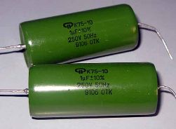
If the frequency is small, for example, the frequency of the lighting network or the frequency of the sound range, then it is quite possible to use paper and paper capacitors.
Paper dielectric capacitors are coated with a thin metal foil, most often aluminum. The thickness of the plates varies between 5 ... 10 μm, which depends on the design of the capacitor. A dielectric of capacitor paper impregnated with an insulating composition is embedded between the plates.
In order to increase the operating voltage of the capacitor, the paper can be laid in several layers. This whole package is twisted like a carpet, and placed in a round or rectangular case. In this case, of course, conclusions are drawn from the plates, and the case of such a capacitor is not connected to anything.
Paper capacitors are used in low-frequency circuits at high operating voltages and significant currents. One of these very common applications is the inclusion of a three-phase motor in a single-phase network.
In metal-paper capacitors, the role of the plates is played by the thinnest metal layer sprayed in vacuum onto a capacitor paper, all of the same aluminum. The design of the capacitors is the same as the paper ones, however, the dimensions are much smaller. The scope of both types is approximately the same: DC, pulsating and alternating current circuits.
The design of paper and metal paper capacitors, in addition to capacitance, provides these capacitors with significant inductance. This leads to the fact that at some frequency the paper capacitor turns into a resonant oscillatory circuit. Therefore, such capacitors are used only at frequencies of not more than 1 MHz. Figure 1 shows paper and paper capacitors produced in the USSR.
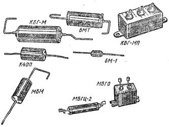
Picture 1. Paper and paper capacitors for AC circuits
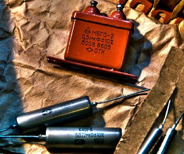
Ancient metal-paper capacitors had the property of self-healing after breakdown. These were capacitors of the MBG and MBGCH types, but now they were replaced by capacitors with a ceramic or organic dielectric of the K10 or K73 types.
In some cases, for example, in analogue storage devices, or in another way, sampling-storage devices (SEC), special requirements are imposed on capacitors, in particular, low leakage current. Then capacitors come to the rescue, the dielectrics of which are made of materials with high resistance. First of all, these are fluoroplastic, polystyrene and polypropylene capacitors.Slightly lower insulation resistance in mica, ceramic and polycarbonate capacitors.
The same capacitors are used in pulsed circuits when high stability is required. First of all, for the formation of various time delays, pulses of a certain duration, as well as for setting the operating frequencies of various generators.
In order to make the time parameters of the circuit even more stable, in some cases it is recommended to use capacitors with an increased operating voltage: there is nothing wrong with installing a capacitor with an operating voltage of 400 or even 630 V in a circuit with a voltage of 12V. Such a capacitor will take up places, of course, more, but the stability of the entire circuit as a whole will also increase.
The electric capacitance of capacitors is measured in Farads F (F), but this value is very large. Suffice it to say that the capacity of the globe does not exceed 1F. In any case, this is exactly what is written in the textbooks of physics. 1 Farad is the capacity at which, with a charge of q per 1 pendant, the potential difference (voltage) on the capacitor plates is 1V.
It follows from what has just been said that Farada is a very large value, therefore, in practice, smaller units are more often used: microfarads (μF, μF), nanofarads (nF, nF) and picofarads (pF, pF). These values are obtained using fractional and multiple prefixes, which are shown in the table in Figure 2.
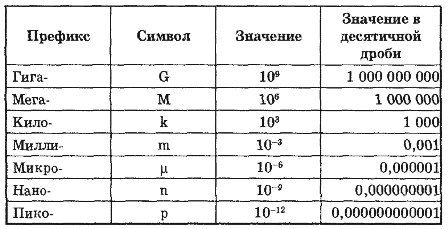
Figure 2
Modern parts are becoming smaller, therefore, it is not always possible to put complete markings on them, more and more they use various systems of symbols. All these systems in the form of tables and explanations for them can be found on the Internet. On capacitors designed for SMD mounting, most often there are no signs at all. Their parameters can be read on the packaging.
In order to find out how the capacitors behave in AC circuits, it is proposed to do some simple experiments. At the same time, there are no special requirements for capacitors. The most common paper or paper capacitors are quite suitable.
Capacitors conduct alternating current
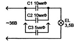
To verify this firsthand, it is enough to assemble a simple diagram shown in Figure 3.
Figure 3
First you need to turn on the lamp through capacitors C1 and C2 connected in parallel. The lamp will glow, but not very brightly. If we now add another capacitor C3, then the luminescence of the lamp will increase markedly, which indicates that the capacitors resist the passage of alternating current. Moreover, a parallel connection, i.e. increase in capacity, this resistance reduces.
Hence the conclusion: the larger the capacitance, the lower the resistance of the capacitor to the passage of alternating current. This resistance is called capacitive and is referred to in the formulas as Xc. Xc also depends on the frequency of the current, the higher it is, the less Xc. This will be discussed later.
Another experience can be done using an electricity meter, having previously disconnected all consumers. To do this, you need to connect in parallel three capacitors of 1 μF and just plug them into a power outlet. Of course, one must be extremely careful, or even solder a standard plug to the capacitors. The operating voltage of the capacitors must be at least 400V.
After this connection, it is enough to simply observe the meter to make sure that it stands still, although it is estimated that such a capacitor is equivalent in resistance to an incandescent lamp with a power of about 50W. The question is, why does not spin the counter? This will also be discussed in the next article.
Boris Aladyshkin
See also at bgv.electricianexp.com
:

