Categories: Featured Articles » Practical Electronics
Number of views: 50959
Comments on the article: 0
Stabilized power supplies
 All electronic equipment is powered by direct current sources. For mobile equipment, batteries or galvanic batteries are typically used. Now there is plenty of such equipment in the hands and pockets: these are mobile phones, cameras, tablet computers, various measuring instruments and much more.
Stationary electronics - televisions, computers, music centers, etc. powered by AC using power supplies. Here, in no case can you do without batteries or small batteries.
Electronic devices are often not stand-alone and work on their own. First of all, these are built-in electronic units, for example, a control unit for a washing machine or microwave. But even in this case, the electronic units have their own Power supplies, most often even stabilized, and even with protection, which allows you to protect both the power supply itself and the load, i.e. connected control unit.
In the designs developed by the amateur radio amateurs, there is always a power supply, unless, of course, this design is brought to the end, and not abandoned halfway. Unfortunately, this happens quite often. But in the general case, the construction of a circuit consists of several stages.
Among them are the development of a circuit diagram, as well as the assembly and debugging of it on a breadboard. And only after obtaining the required results on the breadboard, they begin to develop a capital structure. That's when they develop circuit boards, a housing and a power supply.
In the process of experiments on the breadboard, the so-called laboratory power supplies. The same unit has to be used for commissioning a wide variety of designs, so it should have wide capabilities.
As a rule, this is a unit with regulation of the output voltage, and providing sufficient current. Sometimes the power supply produces several voltages, such units are called multi-channel. An example is a conventional computer power supply or a bipolar source for a powerful UMZCH.
When the power supply is designed for one fixed voltage, for example 5V, it is not bad to provide protection against exceeding the output voltage: if the output stabilizer transistor breaks through, then the circuit that is powered by it can suffer.
Although such protection is not very complex, there are only a few details, for some reason it is not made in industrial circuits, and it is found only in amateur radio designs, and even then not in all. But, nevertheless, there are such protection schemes.
If you look closely at consumer devices, you will notice that all electronic devices are powered by voltages from the standard range. This is, first of all, 5, 9, 12, 15, 24V. Based on these values, a number of integrated stabilizers with fixed voltages are produced.
In appearance, these stabilizers resemble a conventional transistor in a TO-220 package (similar to KT819) or in a D-PAK package for surface mounting. The output voltage is 5, 6, 8, 9, 10, 12, 15, 18, 24V. These voltages are reflected directly in the marking of the stabilizers applied to the body of the device. It might look something like this: MC78XX or LM78XX.
The datasheets say that these are three-output stabilizers with a fixed voltage, as shown in Figure 1.
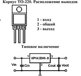
Picture 1.
The switching circuit is extremely simple: they soldered only three legs and got a stabilizer with the required voltage and output current from 1 ... 2A. Depending on the particular stabilizer, the currents vary, which should be noted in the documentation.In addition, integral stabilizers have built-in overheat protection and current protection.
The first two letters indicate the manufacturer's company, and the second XX are replaced by numbers showing the stabilization voltage, sometimes the first two letters are replaced by one ... three or not at all. For example, the MC7805 denotes a stabilizer with a fixed voltage of 5V, and the MC7812 is the same, but with a voltage of 12V output.
In addition to stabilizers with fixed voltages in the integrated version, there are adjustable stabilizers, for example LT317A, a typical switching circuit of which is shown in Figure 2. The limits of voltage regulation are also indicated there.
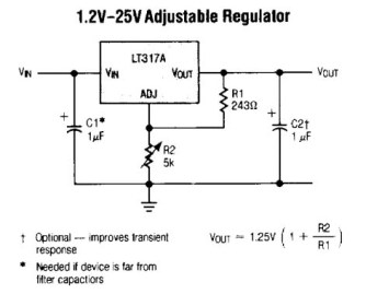
Figure 2. Typical switching circuit of an adjustable stabilizerLT317A
Sometimes there is simply no adjustable stabilizer at hand, how to solve this problem, is it possible to do without it? Well, you need a voltage of 7.5V and that's it! It turns out that a regulator with a fixed voltage easily turns adjustable. A similar switching circuit is shown in Figure 3.
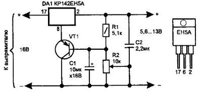
Figure 3
The adjustment range in this case starts from the fixed voltage of the applied stabilizer and is limited only by the magnitude of the input voltage, naturally, minus the minimum voltage drop across the regulating transistor of the stabilizer.
If you do not need to adjust the voltage, but just instead of 5V you need to get, for example, 10, just remove the transistor VT1 and everything connected with it, and instead turn on the zener diode with a stabilization voltage of 5V. Naturally, the zener diode is turned on in a non-conductive direction: the anode is connected to the negative power bus, and the cathode is connected to the stabilizer terminal 8 (2).
Noteworthy is the numbering of the conclusions of the three-legged case, shown in Fig. 3, namely: 17, 8, 2! Where it came from, who invented it, is unclear. Perhaps this is again the machinations of our developers, so that theirs would not have guessed! But such a pinout is used, and one has to put up with it.
After integral stabilizers have been considered, it is possible to proceed to the manufacture of power supplies based on them. To do this, you just need to find a suitable transformer, supplement it with a diode bridge with an electrolytic capacitor, and assemble it all in a suitable case.
Laboratory power supply
Starting to develop a laboratory power supply, you should decide on its elemental base, or, quite simply, what we will make of it from. The easiest way to assemble the desired unit on the LT317A chip or its domestic analogue KR142EN12A (B) is adjustable voltage regulators.
Let's go back to Figure 2. It indicates that the voltage adjustment range is 1.25 ... 25V. The maximum permissible value of this parameter is up to 1.25 ... 37V, with an input voltage of 45V. This is the maximum allowable voltage, so it is better to limit yourself to a 25 volt regulation range.
It is better not to chase the maximum current (1.5A), so we will proceed from the calculation by at least one ampere, which is exactly 75%. After all, the margin of safety should always be. Therefore, for such a power supply you will need rectifier with a voltage of at least 30 ... 33V and a current of up to 1A.
Cthe rectifier circuit is shown in Figure 4. If the current consumption is more than one ampere, the stabilizer should be supplemented with external powerful transistors. But this is another scheme.
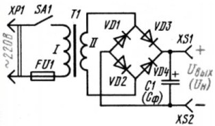
Figure 4. Rectifier circuit
Calculation of rectifier and transformer
First of all, rectifier bridge diodes should be selected, their direct current should also be at least 1A, and it is better if at least 2A or more. Here diodes 1N5408 with a direct current of 3A and a reverse voltage of 1000V are quite suitable. Domestic KD226 diodes with any letter index are also suitable.
The electrolytic capacitor of the filter can also be simply selected using practical recommendations: for each ampere of the output current, one thousand microfarads. If we plan a current of no more than 1A, then a capacitor with a capacity of 1000µF is suitable.Electrolytic capacitors, unlike ceramic ones, do not tolerate increased voltages, therefore, their operating voltage, which should be higher than the real voltage in this circuit, is always indicated in the circuits.
For the designed power supply, a capacitor of 1000µF * 50V is needed. Nothing bad will happen if the capacitor is not 1000, but 1500 ... 2000µF. The rectifier itself is already designed. Now, as they say, the matter is small: it remains to calculate the transformer.
First of all, you should determine the power of the transformer. This is done taking into account the load power. If the output current of the stabilizer is 1A, and the input voltage of the stabilizer is 32V, then the power consumed from the secondary winding of the transformer is P = U * I = 32 * 1 = 32W.
What transformer would be required with such a secondary circuit power? It all depends on the efficiency of the transformer, the greater the overall power, the higher the efficiency. The quality and design of transformer iron also affects this parameter. The table shown in Figure 5 will help determine this question approximately.

Figure 5
To find out the overall power of the transformer, the power in the secondary winding must be divided by the efficiency of the transformer. Suppose that we have at our disposal a conventional transformer with a W-shaped iron, indicated in the table as “armored stamped”. The estimated power of the designed power supply is 32W, then the power of the transformer is 32 / 0.8 = 40W.
As was written just above, for the developed power supply requires a constant voltage of 30 ... 33V. Then the voltage of the secondary winding of the transformer will be 33 / 1.41 = 23.404V.
This allows you to choose a standard transformer with a voltage of the secondary winding at idle 24V.
In order not to complicate the calculations, the voltage drop across the bridge diodes and the secondary resistance of the secondary winding is not taken into account here. It is enough to say that at a current of 1A, the diameter of the secondary wire is usually taken at least 0.6 mm.
Such a transformer can be selected from the unified transformers of the CCI series. The power of the transformer can be more than 40W, this will only improve the reliability of the power supply, although it will slightly increase its weight. If the transformer CCI could not be purchased, then you can simply rewind the secondary winding of the transformer of suitable power.
If a bipolar adjustable power supply is required, it can be assembled according to the circuit shown in Figure 6. For this, a negative voltage regulator KR142EN18A or LM337 will be needed. The circuit of its inclusion is very similar to KR142EN12A.
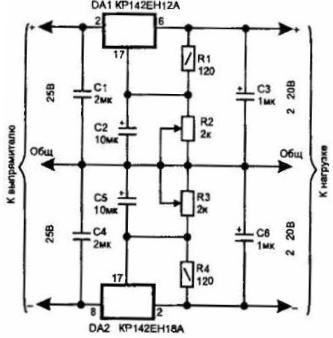
Figure 6. Diagram of a bipolar regulated power supply
It is quite obvious that a bipolar rectifier will be needed to power such a stabilizer. This is most easily done on a transformer with a midpoint and a diode bridge, as shown in Figure 7.
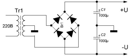
Figure 7. Diagram of a bipolar rectifier
The design of the power supply is arbitrary. The rectifier itself and the stabilizer board can be assembled on separate boards or on one. Microcircuits should be installed on radiators with an area of at least 100 square centimeters. If you want to reduce the size of the radiators, you can apply forced cooling with the help of small computer coolers, of which there are plenty of them on sale now.
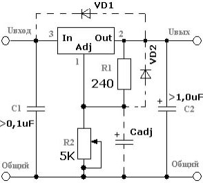
A slightly improved stabilizer switching circuit is shown in Figure 8.
Figure 8 Typical switching circuit KR142EN12A
Protective diodes VD1, VD2 type 1N4007 are designed to protect the microcircuit from breakdown in the case when the output voltage exceeds the input voltage. This situation can happen when you turn off the chip. Therefore, the capacitance of the electrolytic capacitor C2 should not be greater than the capacitance of the electrolytic capacitor at the output of the diode bridge.
The Cadj capacitor connected to the control terminal significantly reduces ripple at the output of the stabilizer. Its capacity is usually several tens of microfarads.
In the design of the power supply, it is desirable to provide a built-in voltmeter and ammeter, preferably electronic, which are sold in online stores. That's just the prices they bite, so at first it is better to do without them, and set the required voltage with a multimeter.
Boris Aladyshkin
See also at bgv.electricianexp.com
:

