Categories: Practical Electronics, Repair of household appliances
Number of views: 26598
Comments on the article: 2
Voltage measurement
 In amateur radio practice, this is the most common type of measurement. For example, when repairing a TV, voltages are measured at characteristic points of the device, namely at the terminals of transistors and microcircuits. If you have at hand a circuit diagram, and it shows the modes of transistors and microcircuits, then it will not be difficult for an experienced master to find a malfunction.
When building self-assembled structures, stress measurement cannot be dispensed with. Exceptions are only classical schemes, about which they write something like this: “If the design is assembled from serviceable parts, then no adjustment is required, it will work right away.”
As a rule, these are classic electronics circuits, for example, multivibrator. The same approach can be obtained even for an audio frequency amplifier, if it is assembled on a specialized chip. As a good example, the TDA 7294 and many more chips in this series. But the quality of the "integrated" amplifiers is small, and true connoisseurs build their amplifiers on discrete transistors, and sometimes on electronic tubes. And here it’s just that you can’t do without adjusting and related stress measurements.
How and what to measure
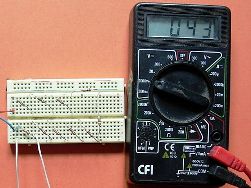
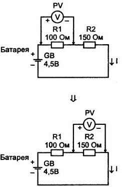
Shown in Figure 1.

Picture 1.
Perhaps someone will say, they say, what can be measured here? And what's the point of putting together such a chain? Yes, it is probably difficult to find practical application for such a scheme. And for educational purposes, it is quite suitable.
First of all, you should pay attention to how the voltmeter is connected. Since the DC circuit is shown in the figure, the voltmeter is connected in accordance with the polarity indicated on the device in the form of plus and minus signs. Basically, this remark is true for the pointer device: if the polarity is not observed, the arrow will deviate in the opposite direction, in the direction of the zero division of the scale. So we get some kind of negative zero.
Digital devices, multimeters, in this regard are more democratic. Even test probes connected in reverse polarity, the voltage will still be measured, only a minus sign will appear on the scale before the result.
Another thing to note when measuring voltages is the measurement range of the device. If the estimated voltage is in the range of, for example, 10 ... 200 millivolts, then the scale of the device corresponds to 200 millivolts, and measuring the voltage on a scale of 1000 volts is unlikely to give an intelligible result.
You should also choose a measurement range in other cases. For a measured voltage of 100 volts, a range of 200V and even 1000V is quite suitable. The result will be the same. It as regards modern multimeter.
If the measurements are made by the good old pointer device, then to measure the voltage of 100V, you should select the measurement range when the readings are in the middle of the scale, which allows for a more accurate reading.
And one more classic recommendation on the use of a voltmeter, namely: if the magnitude of the measured voltage is unknown, then measurements should be started by setting the voltmeter to the largest range. After all, if the measured voltage is 1V, and the range is 1000V, the biggest danger is in the incorrect readings of the device. If it turns out the opposite, the measurement range is 1V, and the measured voltage is 1000, buying a new device simply can not be avoided.
What a voltmeter will show
But, perhaps, we will return to Figure 1, and try to determine what, both voltmeters will show. In order to determine this, you have to take advantage of Ohm's law. The problem can be solved in a few steps.
First, calculate the current in the circuit. To do this, it is necessary to divide the source voltage (in the figure it is a galvanic battery with a voltage of 1.5 V) by the circuit resistance.With a series connection of resistors, this will simply be the sum of their resistances. In the form of a formula, it looks something like this: I = U / (R1 + R2) = 4.5 / (100 + 150) = 0.018 (A) = 180 (mA).
A small note: if the expression 4,5 / (100 + 150) is copied to the clipboard, then pasted into the window of the Windows calculator, then after pressing the "equal" key, the result of the calculations will be obtained. In practice, even more complex expressions containing square and curly braces, degrees and functions are calculated.
Secondly, get the measurement results, like the voltage drop across each resistor:
U1 = I * R1 = 0.018 * 100 = 1.8 (V),
U2 = I * R2 = 0.018 * 150 = 2.7 (V),
To verify the correctness of the calculations, it is enough to add both the resulting values of the voltage drop. The sum must be equal to the battery voltage.
Perhaps someone may ask: “And if the divider is not from two resistors, but from three or even from ten? How to determine the voltage drop on each of them? " In the same way as in the described case. First you need to determine the total resistance of the circuit and calculate the total current.
After which this already known current is simply multiplied by resistance of the corresponding resistor. Sometimes you have to do such calculations, but there is one thing too. In order not to doubt the results obtained, the current in the formulas should be substituted in Amperes, and the resistance in Ohms. Then, without a doubt, the result will be in Volts.
Voltmeter input impedance
Now everyone is used to using Chinese-made devices. But this does not mean that their quality is useless. It’s just that in Russia no one thought of producing their own multimeters, and the arrow testers apparently forgot how to do it. Just a shame for the state.

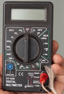
Fig. 2. MultimeterDt838
Once upon a time, the instructions for the instruments indicated their technical characteristics. In particular, for voltmeters and switch testers, this was the input resistance, and it was indicated in kilo-ohms / volts. There were devices with a resistance of 10 K / V and 20 K / V. The latter were considered more accurate, since the measured voltage was reduced less and showed a more accurate result. The above can be confirmed by Figure 3.

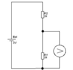
Figure 3
The figure shows voltage divider of two resistors. The resistance of each resistor is 1KΩ, the supply voltage is 3V. It is easy to guess, even it is not necessary to consider anything, that on each resistor there will be exactly half the voltage.
Now imagine that the measurements are carried out by the TL4 device, which in the voltage measurement mode has an input impedance of 10KΩ / V. At the voltage indicated in the diagram, the measurement limit of 3V is quite suitable, at which the total resistance of the voltmeter will be 10 * 3 = 30 (KOhm).
Thus, it turns out that another 30KΩ is connected in parallel with the resistor with a resistance of 1KΩ. Then the total resistance when connected in parallel will be 999.999 Ohm. Although somewhat smaller, but not by much. Therefore, the error of the voltage measurement result will be negligible.
If both resistors of the divider have a nominal value of 1 megaohm, then the calculation results will look something like this:
The total resistance of a parallel-connected voltmeter and resistor R1 will be less than less, and by calculation it will be 29.126KΩ. Whoever does not believe can, for practice, recalculate according to formulas for parallel connection of resistances.
Total current in the divider circuit: I = U / (R1 + R2) = 3 / (1000 + 29.126) = 0.0029150949446423470012418304464176 (mA).
The resistance values are substituted in kilo-ohms, so the current turned out in milliamps. Then it turns out that the voltmeter will show
0.0029150949446423470012418304464176 * 29.126 ≈ 0.085 V.
And half was expected, i.e. one and a half volts! If the current is in milliamperes, the resistance is in kilo-ohms, then the result is obtained in volts. Although not according to the SI system, sometimes they do so.
Of course, such a divider is somewhat unrealistic: why put only 3 megaohm resistors on a voltage of only 3V? Or maybe such a divider is used somewhere, only the voltage on it must be measured with a completely different device.
For example, one of the cheapest Chinese multimeters DT838, on all voltage measuring ranges, has an input resistance of 1 megohm, much higher than the device in the previous example. But this does not mean at all that arrow meters have outlived their age. In some cases, they are simply irreplaceable.
AC voltage measurement
All methods and recommendations related to the measurement of constant voltage are also valid for variables: the voltmeter is connected in parallel to the circuit section, the input resistance of the voltmeter should be as large as possible, the measurement range should correspond to the measured voltage. But when measuring alternating voltages, two more factors should be taken into account, which constant voltage does not have. This is the frequency of the voltage and its shape.
Measurements can be carried out by two types of instruments: either a modern digital multimeter or an “antediluvian” pointer tester. Naturally, both devices in this measurement are included in the mode of measuring alternating voltages. Both devices are designed to measure the voltage of a sinusoidal shape, and at the same time will show rms value.
The effective voltage U is 0.707 of the amplitude voltage Um.
U = Um / √2 = 0.707 * Um, whence it can be concluded that Um = U * √2 = 1.41 * U
A pervasive example is appropriate here. When measuring AC voltage, the device showed 220V, which means that the amplitude value according to the formula is
Um = U * √2 = 1.41 * U = 220 * 1.41 = 310V.
This calculation is confirmed every time when the mains voltage is rectified by a diode bridge after which there is at least one electrolytic capacitor: if you measure the constant voltage at the bridge output, the device will show just 310V. This figure should be remembered, it can be useful in the development and repair of switching power supplies.
The indicated formula is valid for all stresses if they have a sinusoidal shape. For example, after a step-down transformer there is a 12 V change. Then, after straightening and smoothing on the capacitor, we get
12 * 1.41 = 16.92 almost 17V. But this is if the load is not connected. When the load is connected, the DC voltage will drop to almost 12V. In the case when the voltage form is different than the sine wave these formulas do not work, the devices do not show what was expected of them. At these voltages, measurements are made by other instruments, for example, an oscilloscope.
Another factor affecting the voltmeter readings is the frequency. For example, the DT838 digital multimeter, according to its characteristics, measures alternating voltages in the frequency range 45 ... 450 Hz. A little better in this regard is the old TL4 pointer tester.
In the voltage range up to 30V, its frequency range is 40 ... 15000Hz (almost the entire sound range can be used when tuning amplifiers), but with an increase in voltage, the permissible frequency decreases. In the 100V range it is 40 ... 4000Hz, 300V 40 ... 2000Hz, and in the 1000V range it is only 40 ... 700Hz. Here is an indisputable victory over a digital device. These figures are also valid only for sinusoidal stresses.
Although sometimes no data are needed on the shape, frequency and amplitude of the alternating voltages. For example, how to determine if the local oscillator of a shortwave receiver is working or not? Why doesn't the receiver “catch” anything?
It turns out that everything is very simple, if you use a pointer device. It is necessary to turn it on to any limit for measuring alternating voltages and with one probe (!) Touch the terminals of the local oscillator transistor. If there are high-frequency oscillations, then they are detected by the diodes inside the device, and the arrow will deviate to some part of the scale.
See also at bgv.electricianexp.com
:
