Categories: Featured Articles » Practical Electronics
Number of views: 152,245
Comments on the article: 0
About resistors for beginners to do electronics
Continuation of the article about the start of electronics classes. For those who decided to start. A story about the details.
 Amateur radio is still one of the most common hobbies. If at the beginning of its glorious path amateur radio mainly affected the design of receivers and transmitters, then with the development of electronic technology the range of electronic devices and the range of amateur radio interests expanded.
Of course, such sophisticated devices as, for example, a VCR, a CD player, a TV or a home theater at home will not even be assembled by the most qualified radio amateur. But repair of industrial production equipment involved in a lot of amateur radio enthusiasts, and quite successfully.
Another area is the design of electronic circuits or the refinement of “up to luxury” industrial devices.
The range in this case is quite large. These are devices for creating a "smart home", battery chargers, motor speed controllers, frequency converters for three-phase motors, converters 12 ... 220V for powering TVs or sound reproducing devices from a car battery, various temperature controllers. Also very popular photo relay circuits for lighting, security devices and alarmsas well as much more.
Transmitters and receivers have faded into the background, and all the equipment is now called simply electronics. And now, perhaps, it would be necessary to call amateur radio operators somehow differently. But historically, they simply did not come up with a different name. Therefore, let there be hams.
Electronic Components
With all the variety of electronic devices, they consist of radio components. All components of electronic circuits can be divided into two classes: active and passive elements.
Active are radio components that have the ability to amplify electrical signals, i.e. having a gain. It is easy to guess that these are transistors and all that is made of them: operational amplifiers, logic circuits, microcontrollers and much more.
In a word, all those elements in which a low-power input signal controls a sufficiently powerful output. In such cases, they say that the gain (Kus) they have more than one.
Passive components include resistors, capacitors, inductor, diodes etc. In a word, all those radio elements that have Kus within 0 ... 1! The unit can also be considered an enhancement: "However, it does not weaken." Here first, and consider the passive elements.
Resistors
They are the simplest passive elements. Their main purpose is to limit the current in the electric circuit. The simplest example is the inclusion of an LED, shown in Figure 1. Using resistors, the mode of operation of the amplifier stages for various transistor switching circuits.

Figure 1. Switching schemes for the LED
Resistor Properties
Previously, resistors were called resistances, this is just their physical property. In order not to confuse the part with its resistance property, renamed resistors.
Resistance, as a property inherent in all conductors, is characterized by resistivity and linear dimensions of the conductor. Well, about the same as in mechanics, specific gravity and volume.
The formula for calculating the resistance of a conductor is: R = ρ * L / S, where ρ is the resistivity of the material, L is the length in meters, S is the cross-sectional area in mm2. It is easy to see that the longer and thinner the wire, the greater the resistance.
You might think that resistance is not the best property of conductors, well, it simply prevents the passage of current.But in some cases, just this obstacle is useful. The fact is that when a current passes through a conductor, thermal power P = I is released on it2 * R. Here P, I, R, respectively, power, current and resistance. This power is used in various heating devices and incandescent lamps.
Resistors in the circuits
All details on the electrical diagrams are shown using the UGO (conventional graphic symbols). UGO resistors are shown in Figure 2.

Figure 2. UGO resistors
Dashes inside the UGO indicate the dissipation power of the resistor. It should immediately be said that if the power is less than required, then the resistor will heat up, and, in the end, will burn out. To calculate the power, they usually use the formula, or rather even three: P = U * I, P = I2 * R, P = U2 / R.
The first formula says that the power allocated to a section of an electric circuit is directly proportional to the product of the voltage drop in this section by the current through this section. If the voltage is expressed in Volts, the current in Amperes, then the power will be in watts. These are the requirements of the SI system.
Next to the UGO, the nominal value of the resistor resistance and its serial number on the diagram are indicated: R1 1, R2 1K, R3 1.2K, R4 1K2, R5 5M1. R1 has a nominal resistance of 1Ω, R2 1KΩ, R3 and R4 1.2KΩ (the letter K or M can be used instead of a comma), R5 - 5.1MΩ.
Modern resistor labeling
Resistors are currently labeled with color bars. The most interesting thing is that color marking was mentioned in the first post-war magazine "Radio", published in January 1946. It was also said there that this is a new American marking. A table explaining the principle of “striped” marking is shown in Figure 3.

Figure 3. Resistor Labeling
Figure 4 shows SMD surface mount resistors, also called “chip resistors.” For amateur purposes, resistors of size 1206 are most suitable. They are quite large and have decent power, as much as 0.25W.
The same figure indicates that the maximum voltage for the chip resistors is 200V. Resistors for conventional installation have the same maximum. Therefore, when a voltage is expected, for example, 500V, it is better to put two resistors connected in series.

Figure 4. SMD SMD Resistors
Chip resistors of the smallest sizes are available without marking, because there is simply nowhere to put it. Starting from size 0805, a three-digit marking is placed on the “back” of the resistor. The first two are the nominal, and the third factor, in the form of an exponent of the number 10. Therefore, if it is written, for example, 100, then it will be 10 * 1Ohm = 10Ohm, since any number in the zero degree is equal to one, the first two digits must be multiplied by exactly one .
If 103 is written on the resistor, then you get 10 * 1000 = 10 KOhm, and the inscription 474 says that we have a resistor 47 * 10 000 Ohm = 470 KOhm. Chip resistors with a tolerance of 1% are marked with a combination of letters and numbers, and you can only determine the value by using a table that can be found on the Internet.
Depending on the tolerance on the resistance, the values of the resistors are divided into three rows, E6, E12, E24. The values of the ratings correspond to the numbers in the table shown in Figure 5.
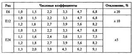
Figure 5
The table shows that the smaller the tolerance on resistance, the more denominations in the corresponding row. If the E6 series has a tolerance of 20%, then there are only 6 ratings in it, while the E24 series has 24 positions. But these are all common-use resistors. There are resistors with a tolerance of one percent or less, so it is possible to find any value among them.
In addition to power and nominal resistance, resistors have several more parameters, but we will not talk about them yet.
Resistor connection
Despite the fact that there are a lot of resistor ratings, sometimes you have to connect them to get the required value. There are several reasons for this: accurate selection when setting up the circuit or simply the lack of the desired rating.Basically, two resistor connection schemes are used: serial and parallel. The connection diagrams are shown in Figure 6. The formulas for calculating the total resistance are also given there.

Figure 6. Connection diagrams of resistors and formulas for calculating the total resistance
In the case of a series connection, the total resistance is simply the sum of the two resistances. This is as shown. In fact, there may be more resistors. Such inclusion happens in voltage dividers. Naturally, the total resistance will be greater than the largest. If it is 1KΩ and 10Ω, then the total resistance will be 1.01KΩ.
With a parallel connection, everything is just the opposite: the total resistance of two (or more resistors) will be less than less. If both resistors have the same rating, then their total resistance will be equal to half of this rating. You can connect a dozen resistors in this way, then the total resistance will be just a tenth of the nominal. For example, ten resistors of 100 Ohms were connected in parallel, then the total resistance was 100/10 = 10 Ohms.
It should be noted that the current in parallel connection according to Kirchhoff’s law is divided into ten resistors. Therefore, the power of each of them will be required ten times lower than for a single resistor.
Read on in the next article.
See also at bgv.electricianexp.com
: