Categories: Featured Articles » Practical Electronics
Number of views: 279,120
Comments on the article: 10
How to check the transistor
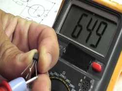 Checking transistors has to be done quite often. Even if you have a deliberately new one in your hands that has never been soldered transistor, then before installing the circuit it is better to check it all the same. There are frequent cases when transistors purchased on the radio market turned out to be worthless, and not even one single copy, but a whole batch of pieces of 50-100. Most often this happens with powerful transistors of domestic production, less often with imported ones.
Sometimes in the design descriptions some requirements for transistors are given, for example, the recommended gear ratio. For these purposes, there are various transistor testers, of a rather complicated design and measuring almost all the parameters that are given in the manuals. But more often it is necessary to check transistors on the principle of "good, bad". It is precisely such verification methods that will be discussed in this article.
Often in a home laboratory, transistors that are in hand, once obtained from some old boards, are at hand. In this case, one hundred percent “input control” is required: it is much simpler to immediately determine an unusable transistor than then to look for it in an idle design.
Although many authors of modern books and articles strongly discourage the use of parts of unknown origin, often enough this recommendation has to be violated. After all, it’s not always possible to go to the store and buy the necessary part. In connection with such circumstances, it is necessary to check each transistor, resistor, capacitor or diode. Next, we will focus mainly on testing transistors.
Amateur transistors are usually tested. digital multimeter or an old analog avometer.
Checking transistors with a multimeter
Most modern hams are familiar with a universal device called a multimeter. With its help, it is possible to measure direct and alternating voltages and currents, as well as the resistance of conductors to direct current. One of the limits of measurement of resistance is intended for the "continuity" of semiconductors. As a rule, a symbol of a diode and a sounding speaker is drawn near the switch in this position.
Before checking transistors or diodes, make sure that the device itself is in good working order. First of all, look at the battery indicator, if necessary, replace the battery immediately. When the multimeter is turned on in the “ringing” mode of semiconductors, a unit in the high order should appear on the indicator screen.
Then check the health instrument probes, why connect them together: zeros will appear on the indicator, and a sound signal will sound. This is not a vain warning, since wire breakage in Chinese probes is quite common, and this should not be forgotten.
For radio amateurs and professional engineers - electronic engineers of the older generation, such a gesture (testing probes) is performed automatically, because when using the pointer tester, each time you switch to the resistance measurement mode, you had to set the arrow to zero scale division.
After these checks are made, you can begin to test semiconductors, - diodes and transistors. Pay attention to the polarity of the voltage across the probes. The negative pole is on the socket labeled “COM” (common), on the socket labeled VΩmA is positive. In order not to forget about this during the measurement, insert a red probe into this socket.
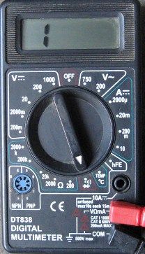
Figure 1. Multimeter
This remark is not as idle as it might seem at first glance.The fact is that with pointer avometers (AmpereVoltOmmeter), in the resistance measurement mode, the positive pole of the measuring voltage is on the socket labeled “minus” or “common”, well, exactly the opposite, compared to a digital multimeter. Although digital multimeters are currently being used more and more, pointer testers are still in use and in some cases provide more reliable results. This will be discussed below.
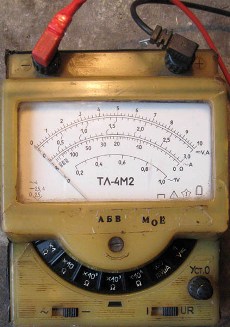
Figure 2. Dial gauge
What the multimeter shows in the "dialing" mode
Diode test
The simplest semiconductor element is diodewhich contains just one P-N junction. The main property of the diode is one-sided conductivity. Therefore, if the positive pole of the multimeter (red probe) is connected to the anode of the diode, then the numbers that show the forward voltage at the P-N junction in millivolts will appear on the indicator.

Figure 3
For silicon diodes, this will be of the order of 650-800 mV, and for germanium diodes of 180-300, as shown in Figures 4 and 5. Thus, according to the readings of the device, it is possible to determine the semiconductor material of which the diode is made. It should be noted that these figures depend not only on the particular diode or transistor, but also on the temperature, with an increase of 1 degree the forward voltage drops by about 2 millivolts. This parameter is called the temperature coefficient of voltage.
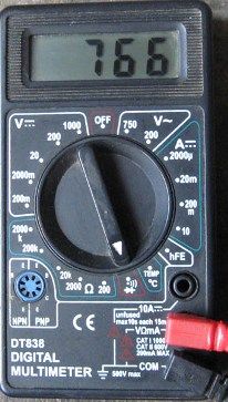
Figure 4
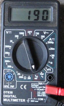
Figure 5
If after this check the probes of the multimeter are connected in reverse polarity, then the unit in the highest order will be displayed on the indicator of the device. Such results will be if the diode is working. That's the whole technique of testing semiconductors: in the forward direction, the resistance is negligible, and in the opposite direction it is almost infinite.
If the diode is “broken through” (the anode and cathode are short-circuited), then most likely a sound signal will be heard, and in both directions. In the event that the diode is “open”, no matter how you change the polarity of connecting the probes, one will glow on the indicator.
Transistor test
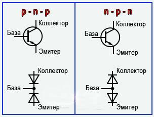
Unlike diodes, transistors have two P-N junctions, and have P-N-P and N-P-N structures, the latter being much more common. In terms of testing with a multimeter, a transistor can be considered as two diodes connected in counter-series fashion, as shown in Figure 6. Therefore, testing transistors reduces to “ringing” the base – collector and base – emitter junctions in the forward and backward directions.
Therefore, all that was said a little higher about the diode test is also completely true for the study of transistor transitions. Even the readings of the multimeter will be the same as for the diode.
Figure 6
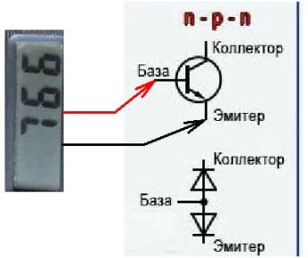
Figure 7 shows the polarity of turning on the device in the forward direction for “ringing” the base-to-emitter transistor of the N-P-N structure: the positive probe of the multimeter is connected to the base terminal. To measure the transition base - collector, the negative terminal of the device should be connected to the output of the collector. In this case, the number on the scoreboard was obtained when the base-to-base emitter of the KT3102A transistor was dialed.
Figure 7
If the transistor turns out to be a P-N-P structure, then the minus (black) probe of the device should be connected to the base of the transistor.
Along the way, you should “ring” the collector-emitter section. A working transistor has almost infinite resistance, which symbolizes a unit in the highest category of the indicator.
Sometimes it happens that the collector – emitter transition is broken, as evidenced by the sound of the multimeter, although the base – emitter and base – collector transitions “ring” as if normal!
Checking transistors with an avometer
It is produced in the same way as with a digital multimeter, but one should not forget that the polarity in the ohmmeter mode is opposite to that in the constant voltage measurement mode. In order not to forget this during the measurement process, the red probe of the device should be included in the socket with the “-” sign, as shown in Figure 2.
Avometers, unlike digital multimeters, do not have a “ringing” mode of semiconductors, therefore, in this regard, their readings differ markedly depending on the specific model. Here you already have to rely on your own experience gained in the process of working with the device. Figure 8 shows the measurement results using the TL4-M tester.
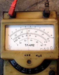
Figure 8
The figure shows that measurements are taken at the limit of * 1Ω. In this case, it is better to focus on the readings not on the scale for measuring resistance, but on the upper uniform scale. It can be seen that the arrow is in the region of figure 4. If measurements are taken at the limit of * 1000Ω, then the arrow will be between the numbers 8 and 9.
Compared with a digital multimeter, the avometer allows you to more accurately determine the resistance of the base-emitter section if this section is shunted by a low-resistance resistor (R2_32), as shown in Figure 9. This is a fragment of the circuit of the output stage of the ALTO amplifier.

Figure 9
All attempts to measure the resistance of the base - emitter section using a multimeter lead to the sound of the speaker (short circuit), since the 22Ω resistance is perceived as a short circuit by the multimeter. The analog tester at the measurement limit * 1Ω shows some difference when measuring the base-emitter transition in the opposite direction.
Another pleasant nuance when using the pointer tester can be found if measurements are taken at the limit of * 1000Ω. When connecting the probes, of course, observing the polarity (for the transistor of the N-P-N structure, the positive output of the device on the collector, minus on the emitter), the arrow of the device does not move, remaining at the scale mark infinity.
If you now slit the index finger, as if to check the heating of the iron, and close the conclusions of the base and collector with this finger, then the arrow of the device will move, indicating a decrease in the resistance of the emitter-collector section (the transistor will open slightly). In some cases, this technique allows you to check the transistor without evaporating it from the circuit.
This method is most effective when checking composite transistors, for example, CT 972, CT973, etc. It should not be forgotten that composite transistors often have protective diodes connected in parallel with the collector-emitter junction, and in reverse polarity. If the transistor of the structure is N-P-N, then the cathode of the protective diode is connected to its collector. Inductive load, for example, relay windings, can be connected to such transistors. The internal structure of the composite transistor is shown in Figure 10.
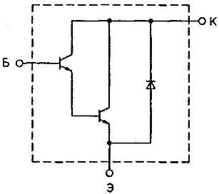
Figure 10
But more reliable results on the health of the transistor can be obtained using a special probe for testing transistors, about which you can see here: Transistor Test Probe.
Boris Aladyshkin
See also at bgv.electricianexp.com
:

