Categories: Practical Electronics, Repair of household appliances
Number of views: 109075
Comments on the article: 31

How to repair a Chinese chandelier - the story of one repair
 

How to repair a Chinese chandelier - the story of one repairIn the article "How to control a chandelier in two wires" various schemes were considered, allowing switching several groups of lamps. The operation algorithm for all circuits is the same: with a short click of the switch, the first group lights up, with the second second, with the third click both groups at once. To turn off the chandelier, switch the switch, as usual, to the open position.

All the circuits considered at different times were developed by radio amateurs. In Chinese-made chandeliers, such devices are already installed, and in addition to them there are some additional lighting and even sometimes sound effects. My colleague at work was engaged in the repair of one of these devices: until you are busy repairing production equipment, you can work hard for yourself. And the defect of the mentioned device was like this - no matter how you click the switch, nothing turns on. Still managed to repair the circuit, but in a somewhat unusual way. Moreover, the defect itself was not understood by us. But first things first.

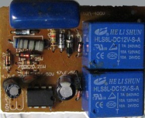
In appearance, the device is quite simple. There are two relays, a microcircuit, and several parts on the board that are slightly larger than the matchbox. The appearance of the board is shown in Figure 1.

Appearance of the board of the Chinese chandelier

Figure 1. The appearance of the board of the Chinese chandelier


Chinese DATASHEET

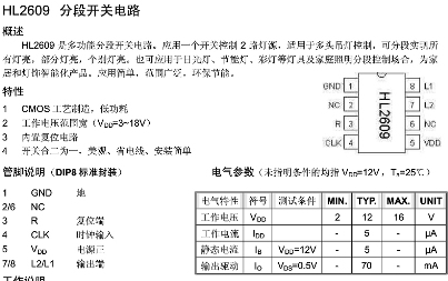
It was natural to assume that all the logic of work is hidden in the HL2609 chip. Searching for familiar sites with datasheets yielded nothing: we could not find the chip anywhere. But as a result of searches in Google and Yandex, it was still possible to find a mysterious stranger. True, the description was in Chinese, which was actually expected.

It was not possible to download it, as usual, in * .pdf format, so I had to be content with screenshots - screenshots. In total, there were three such screenshots, the first of which is shown in Figure 2.

Pinout and operating modes of the HL2609 chip

Figure 2. Pinout and operating modes of the HL2609 chip.

If you do not pay attention to the hieroglyphs, then from this figure you can draw the following information.

Firstly, we have an HL2609 chip in the DIP-8 package. Secondly, this is a microchip of the CMOS structure (in the Russian version it is also a CMOS), is operable in the range of supply voltages 2 ... 16V, with a maximum output current of up to 70mA. It also shows the pinout (a more modern, somewhat slang term - pinout) of the microcircuit.

Power is supplied between 1 and 5 pins, the load (L1, L2) is connected to pins 7 and 8, pins 2 and 6, designated as NC (No Connect) inside the microcircuit are not connected anywhere.

Pin 3, denoted as R, is the reset of the microcircuit to its initial state when it is first turned on, and pin 4 of CLK is a clock pulse that changes the state of the microcircuit during subsequent short-term clicks of the switch.

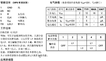
Figure 3 in the bottom table shows the logic of the microcircuit (truth table). She does not need detailed explanations.

The logic of the chip HL2609

Figure 3. The logic of the HL2609 chip.

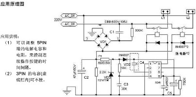
On the same page of the Chinese datasheet is a diagram of the entire device, apparently, as a typical switching scheme. It is shown in Figure 4. Unfortunately, the internal structure of the microcircuit is not shown, but how could it help during the repair?

Typical HL2609 chip wiring diagram

Figure 4. Typical HL2609 circuitry.


How it should work

Details on the diagram, as well as on the board itself, do not have standard designations, such as R1, R2, C1, etc. Therefore, to simplify the description, in the diagram this numbering had to be done additionally. Part numbers are shown in Figure 4.

The entire circuit is powered by a transformerless rectifier VD1, made according to a bridge circuit with blanking capacitor C1.When you turn on the device for the first time (1 column of the truth table), until capacitor C2 is charged, capacitor C3 has a low voltage, which resets the microcircuit to its initial state, both relays are off, the lamps naturally do not light. Further, the capacitor C3 is charged to a high level and is not affected by the further operation of the circuit.

At the same time, the capacitor C5 is charged, which provides power to the chip for a short click of the switch to switch groups of lamps. With each click, a clock pulse is generated on the capacitor C4, and the relay switches according to the truth table shown in Figure 3.

Since the capacitor C2 does not have time to completely discharge during a short click, the reset pulse on the capacitor C3 is not formed and the device does not return to its original state. The chandelier is turned off as usual, which corresponds to the last column of the truth table.

Everything seems to be simple, clear and understandable, but, as the classic used to say ...


“And turn it on - does not work!”

The scheme of the device and the logic of its operation are simple and clear, it would seem that there is simply nothing to not work in it. And yet…

External manifestation of the defect - not a single group of lamps is turned on. Checking parts, diodes and resistors, a multimeter did not find faulty parts. Capacitors were checked simply by replacement method. What was the conclusion from here? The chip is to blame.

When examining the circuit, it turned out that the relays seemed to be trying to turn on, and the switching sequence completely corresponded to the truth table shown in Figure 3. But switching on did not occur completely: on terminals 7 and 8, the voltage dropped only to 5 volts. But with fully open output transistors, the voltage at these terminals should be no more than 0.5V.

By the way, the voltage across the capacitor C2 also "sagged" to 5V. An increase in the capacity of the quenching capacitor C1 also did not lead to the elimination of the defect. Also, a diode bridge was checked by replacement. No positive effect was achieved.

Research has been continued. Instead of a relay, LEDs were connected, of course, with limiting resistors. When the switch clicks, the LEDs light up and go out in the required sequence shown in the truth table. That seems to be the way to solve the problem! It is necessary to put an optocoupler with a transistor, such a kind of amplifier, which will control the operation of the relay. These experiments are shown in Figure 5.

Figure 5

The reasoning was as follows. A faulty microcircuit cannot turn on the relay, and the optocoupler LED should offload the output stage of the microcircuit. The transistor at the output of the optocoupler will easily and unconditionally turn on the relay. But our surprise knew no bounds when this revision still did not turn on the relay. It would seem that the experiments have reached an impasse and further continuation does not make sense.

The problem was solved by a completely different method. The circuit was restored to its original state, and an additional source was connected in parallel to the capacitor C2, just a suitable 12V transformer with a rectifier bridge.

After such an addition, the circuit worked, as expected, the entire switching algorithm is fully implemented. Still, the problem lies inside the chip, but it is unlikely to buy one. Therefore, here you can only repeat the hackneyed phrase that all means are good for achieving the result. The additional connections made are shown in Figure 6.

Figure 6

Boris Aladyshkin

See also at bgv.electricianexp.com:

  • Two-wire chandelier control circuits using semiconductors
  • How to control a chandelier in two wires. Relay circuits
  • Logic chips. Part 2 - Gates
  • Logic chips. Part 9. JK trigger
  • Simple power control for smooth lamp on

  •  
     
    Comments:

    # 1 wrote: Vadim | [quote]


    Strange. You concluded: "Still, the problem lies inside the chip."

    The changes made to the circuit apply only to the power of the entire device, and the chip is to blame.

    Rather, the standard rectifier does not provide enough current to trip the relay.

     
    Comments:

    # 2 wrote: Vlad | [quote]


    Somehow, everything is very complicated. Repairing a Chinese chandelier is a serious thing! You can’t figure it out without a hundred grams ... I liked the pictures with Chinese characters. I have long been convinced - the Chinese are ahead of the rest! We still have radio amateurs just inventing something, and they already have chandeliers stuffed with electronics on an industrial scale, and they fill up the whole world with them. Miracles and more! It’s time to start learning Chinese little by little, otherwise we will lag behind technological progress winked

     
    Comments:

    # 3 wrote: | [quote]


    I understand a little of what is in these schemes, nevertheless it is very interesting!

     
    Comments:

    # 4 wrote: | [quote]


    The circuit will additionally consume energy, although not much. But, for example, if the apartment has three televisions and everything is constantly in standby mode, then the difference in the payment for electricity is already noticeable. smile

     
    Comments:

    # 5 wrote: | [quote]


    Most likely, the contacts in the reels were burned, and when they were weakly fed according to the native Chinese scheme, they did not provide sufficient clamping force to “break through” the soot, well, and feeding them from 12V external for some time would resume their operation. The Jesuit way to bring the product out of working condition after the warranty period. And the reels, go, are non-separable ;-) Previously, they usually put spark-extinguishing chains parallel to the contacts - series resistance and capacitance, well, and without them - a typical Chinese product.

     
    Comments:

    # 6 wrote: novel | [quote]


    replace c1 c2 or increase capacitance c1 to 1.5 uF

     
    Comments:

    # 7 wrote: ivan | [quote]


    But how to do so that it does not reset the chip to its initial state?

     
    Comments:

    # 8 wrote: | [quote]


    The HL2609 chip is most likely a set of transistors (2 pcs). And it works like keys. You can read about the transistor key - "industrial electronics". I have never seen such a chandelier.

     
    Comments:

    # 9 wrote: Boris Aladyshkin | [quote]


    viktor, no, this is not a set of two transistors. The logic of operation is very similar to a two-bit binary counter. For each counting pulse, its state increases by 1. In binary code, it looks like this: 00, 01, 10, 11 and then again 00 - 11. 1 in this record corresponds to the lamp on. In addition to the counting input, there is a reset input and two fairly powerful outputs.

     
    Comments:

    # 10 wrote: | [quote]


    In 2011, I first encountered this problem. Google did not help, there was no information. Chandelier did not respond to the remote control. I remember changing the heel to domestic (I wound it with electrical tape to the body). It is quite successful that a multimeter without problems revealed that Chinese goods are rare. Moreover, some kind of capacitor was leaking (if I am not mistaken, the microfarad) - the radio signal worked at a distance of 1 meter. This year, another chandelier rang, and everything did not work. An exception method is a microcircuit. He cured by buying a new remote control for 400 rubles. Thanks for the article - I'm sure it will come in handy.

     
    Comments:

    # 11 wrote: | [quote]


    Interesting. I really have a slightly different problem, only one type of light works blue diodes (not enough for lighting the room) does not switch to another type. The scheme with the reels is almost the same.

     
    Comments:

    # 12 wrote: Alexander | [quote]


    Thanks to the author for the detailed article! He similarly cured by tossing an external power source, though the changes in front of the rectifier diodes with the evaporation of the capacitor C1 and the resistor 330kom

     
    Comments:

    # 13 wrote: | [quote]


    We have a slightly different problem. When you turn off the light, in one mode, and turn it on in another. That is, our chandelier is lit in different colors. And when you sharply enter the room and press the switch, it turns on either color or white light. Very inconvenient, you have to turn around and click many times until what you need is turned on. Is there anything you can do about this?

     
    Comments:

    # 14 wrote: | [quote]


    I wonder how in these chandeliers the coding for a specific remote control is set !!!?

     
    Comments:

    # 15 wrote: Boris Aladyshkin | [quote]


    Alina, you, apparently, have a completely different chandelier, not similar to the one in the article. Maybe you just need to give her a “rest” for a minute or two so that she returns to her initial state: most likely the capacitor in the power source does not have time to discharge, or the one that is in the initial reset circuit. Therefore, the cycle does not start from the beginning, but from anywhere.

    Valentine, To answer your question, perhaps, the article “Do-it-yourself remote control repair.” Part 1. Development History and Remote Control Device ”, published on the site - bgv.electricianexp.com/main/praktika/632-istoriya-razvitiya-i-ustroystvo-pdu.html There is also the second part of the article.

     
    Comments:

    # 16 wrote: | [quote]


    Same problem. It does not turn on. But when tapping the relay there is a blink. I will try to replace the relay with HRS4H-S-DC12V. The circuit uses a TC2608 chip. The description is also only in Chinese. She has three relays. The board and placement of items is similar.
    That's just on it, probably, and you can choose which group to include (L1, L2 or L3) using the switch S, closing to R or L.

     
    Comments:

    # 17 wrote: | [quote]


    I also have a problem with such a switch, however, for three consumers. At first, the chandelier simply stopped responding to the remote control and to the switch. I removed the block, two of the three relays worked properly. I did not work, I re-soldered, everything worked, and when I put it in place, then the first couple of inclusions everything was in order, and then the bobik died and did not react at all. In electronics, I'm almost zero. Tell me, please, where to start? I rang the diodes, did not solder anything, and did not check.

     
    Comments:

    # 18 wrote: prophecy | [quote]


    And yet the chip is not at work.

     
    Comments:

    # 19 wrote: | [quote]


    And how to consider the issue - when you discard the in4007 isolation diode in the microcircuit's power supply to hold it to the next switching pulse of the circuit breaker in the idle block with the diode on the Zener diode 4 in without without 12v at the output m \ s + 2v it is better to recall the operation diagrams of m \ s with power 12c, it can be decoders or a trigger and put a little circuit in the place of nl-2608 in its holes. As if there were no bauds of the m / s operation diagrams, but before, he himself was engaged in the design of electronic units \ and his vision is not so much that he can mount m / s. Are we stupider than the Chinese?

     
    Comments:

    # 20 wrote: | [quote]


    Good afternoon Boris! You yourself answered your own question! I have exactly the same problem with the same circuit. I just threw the food from the side and it worked. BUT, it didn’t suit me. In short, the problem was in the power supply, namely in capacitor c1. choosing the necessary calculations, everything worked, namely - 105J 400 V without a remote control (such as your picture) and the second unit with a remote control of 2.2 microfarads. 400 volts. when I tried to replace it with the same capacitor as it was, nothing worked for me either. dig in the direction of the quenching capacitor. The main thing is to correctly calculate the current load.

     
    Comments:

    # 21 wrote: Oleg | [quote]


    Thanks!!! How much time has been spent! But a very useful article.

     
    Comments:

    # 22 wrote: | [quote]


    What are you tormented by? Now there are no problems with the masters. You type in Yandex: "repair of chandeliers with a remote control the name of your city." They will do everything and explain.

     
    Comments:

    # 23 wrote: | [quote]


    Tell me please. When I turn on the switch, I have one relay all the time and immediately disappears, i.e. does not react to the remote control in any way. KD3 chandelier control relay type for three loads.

     
    Comments:

    # 24 wrote: | [quote]


    The problem was solved after replacing the input capacitor 105j was 4.5v put 564j the voltage rose to 10.5v the relay works confidently. did not continue to experiment. Thanks to your article.

     
    Comments:

    # 25 wrote: Nikolay | [quote]


    I have a similar thing, but with a remote control. How to remove the mode switch by the switch, and so that the switching works only from the remote control?

     
    Comments:

    # 26 wrote: Maza | [quote]


    Tell me, can anyone come across? I have already changed 2 zener diodes to 5v.The circuit works for 1 minute, I checked the electrodes in the strapping, the norm

     
    Comments:

    # 27 wrote: Vladimir | [quote]


    There was also a problem with the two-channel chandelier - only blue LEDs were on. An autopsy showed that there was a short circuit in the light bulbs, i.e. in the load, from which half of one relay output burned out. I swapped two relays in places, soldering a thin wiring from a charred relay output to payment (otherwise it did not reach the board). Everything worked. Wounded relyushka now stands at low current load. Inside is a 2608 chip.

     
    Comments:

    # 28 wrote: Sergei | [quote]


    The same disgust I only have a TC2608 chip. The zener diode flew out. Replaced, started scribbling relyuhi. As a result, the zener diode was removed, everything else was as it was, it works as expected.

     
    Comments:

    # 29 wrote: Oleg Lepkov | [quote]


    Kapets repairmen, "Still, the problem lies inside the microcircuit." Yes, in the capacitor it is covered C1 decreased capacity (dry), that's all, it was necessary to replace it with a working one, and not another collective power supply unit and optocouplers. But in general, the article is good, thanks.

     
    Comments:

    # 30 wrote: Sergey Arestovich | [quote]


    Oleg Lepkov,
    This block on Ali costs $ 2, if there is time, you can tinker with it, and so is the point?

     
    Comments:

    # 31 wrote: Denis | [quote]


    Danil,
    100% --- C1 !!!!