Categories: Featured Articles » Practical Electronics
Number of views: 29541
Comments on the article: 4
Computer technology in the service of a radio amateur
The computer is also a radio amateur tool
 For many people, a computer is not only a home entertainment center, but also a tool to make good money. First of all, these are, of course, programmers. People of other professions are not without a computer: writers, translators, architects, designers, designers, accountants, and even musicians. This list is probably endless these days.
IN amateur radio workshop the computer is not the last place. First of all, this is a repository of various literature, which used to occupy a lot of space in a bookcase. Working with books and magazines has become much easier and faster: the right book or article is in seconds. And what about online libraries!
About details and technical issues
If it is not possible to solve a technical issue on their own, then you can "go" to the Internet - forum of radio amateurs and solve the problem, as they say, without leaving home. Without leaving home, you can also purchase parts in the online store. One of the best radio parts stores is Elitan.
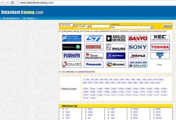
Given that the element base is now mostly bourgeois, one often has to search the Internet for information on radio components, these are the so-called Datasheets (Data Sheet). If there is no circuit when repairing an electronic device, then the Data Sheet helps a lot: at least, you can determine where the microcircuit has what conclusions and what it does in the device in general. And if you recall at least a little English from the school curriculum, it will be generally gorgeous.

Fig. 1. Search datasheet
But what if the part is tiny, for example SMD (Surface-Mounted Device - parts for surface mounting)? Only two to three letters are indicated on the surface of such parts. Using these letters with the help of special programs or tables, the full name of the component is determined, and the corresponding Data Sheet is already found on it.
Amateur Radio Computer Programs
There are a lot of these programs, and most often they are free or their demo versions are quite sufficient for amateur use. It is simply impossible to talk about all the programs in one article, so only a few will be listed here.
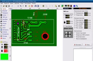
First of all, these are programs for PCB layout. The most accessible and easy to use group of programs is sprint-layout. Now the sixth version has already been released. The program of this version has a Russian-language interface and help in Russian. Although the user interface is so simple and intuitive that help is simply not necessary.
After the board is divorced, it is printed on a laser printer and on LUT (laser ironing technology) make a printed circuit board. A lot has already been written about this, so we can go further.

Fig. 2. Work in the program sprint-layout
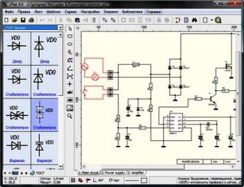
The graphical program sPlan_6.0.0.2_Portable will assist in the implementation of the concepts. Everything is very simple there: from the ready-made elements (resistors, transistors, capacitors, microcircuits), a simple drag and drop with a mouse makes up a circuit diagram.
Naturally, all elements are connected by conductors. Such a drawing machine is very convenient when repairing equipment when there is no circuit, and it has to be copied from a printed circuit board: erroneous elements are very simple and easy to remove, various corrections are made. The end result will be a beautiful pattern printed on paper.

Fig. 3. Work with electronic circuit in sPlan program
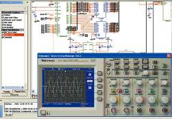
There are programs that allow you to investigate the operation of electronic circuits without a soldering iron. One such program is Electronics WorkBench (Electronic Workshop) EWB. Here, too, with the help of the mouse, you can assemble a circuit that looks similar to the principal one.But when you press the power button, the circuit starts to work, which can be seen with the help of devices located in the same program. For example, by applying a signal from the generator to the amplifier input, look at the screen of the virtual oscilloscope for the signal to pass through all stages.

Fig. 4. Virtual Oscilloscope

Fig. 5. The program for the design and study of electronic circuits
Many hams design their circuits using microcontrollerstherefore, they have to use various programming environments, programmers for “flashing” controllers to write working programs. All this also without a computer is simply impossible to do.
But even without a real microcontroller at hand, you can develop programs. Proteus, a computer simulation system, will help. Of course, the program model is somewhat different from the real controller, but in general, this is quite enough to debug program algorithms.
Boris Aladyshkin
P.S. Video on the topic. Search Data sheet.
We work in Sprint Layout - creating a board from a bad picture:
See also at bgv.electricianexp.com
:
