Categories: Featured Articles » Practical Electronics
Number of views: 85003
Comments on the article: 7
The electrical circuit of the power supply for the garage
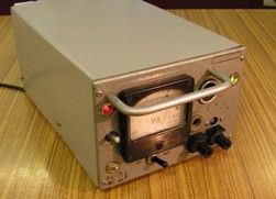
 Let me remind you that this is a diagram of a specific device instance (see: Garage power supply) and some of its parts may look redundant, and the parameters of individual elements with a large margin. Nevertheless, it was tuned and adjusted to the actual operating conditions and is fully operational.
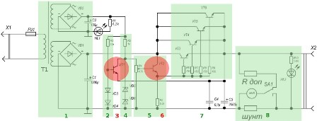
The purpose of the individual elements of the circuit and the operation of the device is more convenient to consider in the following block diagram.
1. Transformer and rectifiers;
2. The voltage reference driver for a short-circuit protection circuit;
3. Active element of protection against short circuit;
4. Shaper of the reference voltage for the stabilization circuit and adjust the output voltage;
5. The node for adjusting the output voltage;
6. The active element of the stabilization and adjustment of the output voltage;
7. Regulating transistors;
8. The node display parameters of the output voltage.
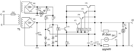
Fig. 1. Electrical diagram of the power supply for the garage (click on the picture to enlarge)
Fig. 2. Block diagram of the power supply (click on the picture to enlarge)
Work circuit:
Rectifiers:
The input voltage of 220 volts through the fuse goes to the transformer winding (primary). The lower secondary winding of the transformer (block 1) is made of thick wire and is marked 8-8 ', the voltage from this winding will be used to power the load. A diode bridge assembled on powerful D231 diodes (Imax = 10A) rectifies the voltage. Voltage ripple smoothes capacitor C1. Below is a diagram of a diode bridge assembled on D231 diodes.
Similarly, a rectifier is assembled on the VD2 diode assembly to obtain reference voltages. LED HL1 - to indicate the presence of mains voltage at the input of the power supply. The current through it is limited by the resistor R1.
Operation of the output voltage stabilization circuit
Node 4 is the parametric stabilizer proper on the resistor R2 and zener diodes VD5, VD6. A stabilization voltage of 18 volts has been selected to expand the limits of regulation of the output voltage.
By a variable resistor R4, the voltage based on VT2 can be adjusted. Accordingly, the voltage on its emitter will change, and therefore on the bases connected in parallel output transistors, which in turn will lead to a change in the output voltage.
The circuit will now strive to maintain the set output voltage level. To ensure greater stability, the parametric stabilizer is powered by a separate winding 5-15.
Short circuit protection circuitry
During normal operation of the device, the transistor VT1 is closed and does not interfere with the operation of the output voltage stabilization circuit. Diodes VD3, VD4 are used as zener diodes, as they are turned on in direct polarity, that is, they are constantly open. When current flows through an open diode, about one volt drops on it. Thus, the base of the transistor VT1 has a fixed potential of about two volts. The voltage at the emitter of the transistor is equal to the output voltage (the emitter is connected to the output).
If a short circuit occurs in the load, the output voltage (and hence the emitter VT1) will drop sharply and become less than the voltage on the basis of VT1, the transistor VT1 will open by shunting the resistor R4 (the voltage on the basis of VT2 will drop to almost zero), which will close the transistor VT2 onwards - closing VT3 - VT6. The current through closed transistors is minimal and can no longer damage them.
After eliminating the short circuit, the circuit will return to normal operation.
Power Supply Parts
Transformer TSA-270-1
The VD1 diode bridge is assembled on D231 diodes, you can use any rectifier diodes for currents up to 10 amperes, for example: 10A02 (U = 100B, I = 10A), KD213 (U = 200B, I = 10A).
The VD2 diode bridge is assembled on 1N4007 diodes, you can apply any voltage of 100 volts (because the alternating voltage on the winding is 5-15 = 70 volts), for example: KD221 with any letter (U≥100B, I = 0.5A).
Diodes VD3, VD4 - KD522, you can choose other silicon, for example: D226, KD106
Zener diodes VD5, VD6 - D814B can be replaced by one or more connected in series to obtain the required stabilization voltage, for example: KC509B (Ustab = 18V).
Transistors VT1 - KT312, VT2 - 2T608A, VT3 – VT6 - KT829. Instead of these types, other reverse conductivity transistors of small, medium and high power are quite applicable. For example: KT503E, KT603A, KT819A.
Indicator LEDs - any of those available, are used - AL307BM and VM.
Nikolay Martov
See also at bgv.electricianexp.com
:


