Categories: Practical Electronics, Electrical connection of equipment, Safety precautions
Number of views: 100849
Comments on the article: 17

Isolation transformer in a home electrician workshop


How the isolation transformer works
Isolation transformer in a home electrician workshopAn isolation transformer is a transformer that is designed for electrical (experts say - galvanic) separation of the power supply network and the consumer of electricity. Consumers are us and why divide us? For safety!

The main task of the isolation transformer is to increase electrical safety due to the fact that its secondary circuits do not have electrical connection with the ground, and therefore with the grounded neutral of the transformer substation - a voltage source.

In this case, the occurrence of an electrical breakdown on the case does not cause overcurrents, and the device itself remains in working condition. If a person accidentally touches a part of a device that is accidentally energized, the leakage current will not exceed a life-threatening threshold and tragedy will not happen.
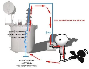
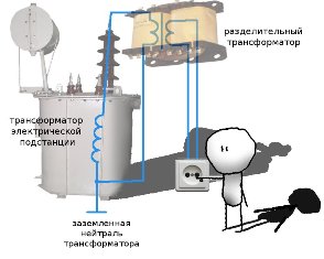
How the isolation transformer works

Isolation transformer - to the home workshop

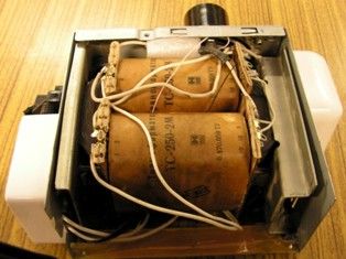
Thus, isolation transformer far from superfluous element in home workshop, especially if he has to deal with the repair of household appliances. Non-industrial isolation transformers are not on sale, but it is not difficult to make one yourself on the basis of a suitable transformer from domestic televisions of the past generation.

Will fit unified transformer TS almost any power, since modern electrical assistants at home do not differ much voracity. The alteration method is universal and does not require special skills, and therefore, everyone who knows how to handle a soldering iron and measure voltage can afford it.

For an example I will give a ready-made design based on TS-250M.

Isolation transformer - to the home workshop

How to make an isolation transformer

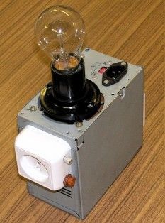
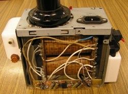
The finished transformer is housed in a case from a computer power supply and is supplemented by some more functions, about which later. A complete TC-250 diagram is shown below.

How to make an isolation transformer

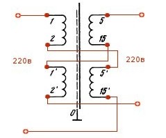
Consider a fragment of the circuit that interests us and which will be modernized. In the standard scheme, two half-windings 1- 2 and 1 '-2' are connected in series and are connected to a 220 volt outlet. (Half-windings are a word meaning that each winding of a transformer is divided into two identical parts, and these half-windings are placed on two identical frames, as in the photo above. On new transformers, the windings are not connected to each other).
How to make an isolation transformer

Accordingly, a voltage of 208 volts is removed from the half-windings 5-15 and 5'-15 '(according to the transformer passport) to power the secondary circuits. Actually on the given instance, this voltage was 216 volts at idle. It is easy to guess that each of the primary half-windings is designed for 110 volts, and the secondary ones for 104 volts (108 volts).

The change in the circuit shown below will allow you to get 220 volts at the transformer output. Now, 1-2 and 5'-15 'are used as primary transformer semi-windings, and 1'-2' and 5-15 as secondary semi-windings. Due to the identity of the winding data of the pairs of semi-windings, the input and output voltages will always be equal. Fig. 6

It should be borne in mind that the power transmitted to the load by the transformer is now limited by the power of the winding with a lower permissible current. In the case under consideration, for a winding 5-15 (5'-15 '), the maximum current is 0.8 amperes, which means that the maximum power according to the formula P = I x U is limited and equal to P = 0.8 A x 220 V = 176 W.


In practice, such power will be abundant in most cases. One should also not be afraid of troubles due to the fact that 110 volts are supplied to the semi-winding 5'-15 'instead of the calculated 104-x.Firstly, the transformer will still work in light, underloaded mode (176 watts instead of 250), and secondly, the letter M in the transformer marking indicates that the transformer is resistant to overloads and overvoltages.

We return to the specific design of the isolation transformer.

How to make an isolation transformer

The photo shows a socket for connecting a load with a fuse and an indicator lamp in the socket. And for what, then, a cartridge with an incandescent lamp on the upper plane, you ask? The answer is a revision that significantly expands the capabilities of the device.


Additional functions of the isolation transformer

The essence of the refinement is clear from the diagram below.

Additional functions of the isolation transformer

The lamp is connected in series in the primary winding of the transformer, but can be shunted by the switch remaining here from the computer power supply. In this case, we have a conventional isolation transformer. With the switch open, the transformer turns into a scan tool.

With its help, it is now easy to carry out simple operations about troubleshooting devices with switching power supplies. Consider this on the example of a television. To do this, connect it to the outlet of a transformer connected to the network, the switch is open. We turn on the TV with the remote control or the button and fix the lamp behavior:

- nothing happens - a break in the power cord, the input fuse of the TV burned out, the input circuit of the power supply burned out;

- when the TV is turned on, the lamp lights up with a steady full light - a short circuit in the power cord, in the input circuits of the power supply;

- the lamp flashed brightly and went out - the power supply is working, you need to check the main board of the TV.

It should be noted that checking the device (TV, in this case) occurs in a sparing mode and does not lead to further damage to the device under test.


Undervoltage AC for testing high voltage circuits

Have you ever checked a 220 volt electrical circuit? After all, is truth dangerous? With the help of an additional transformer output of ~ 36 volts, this can be done without any risk to health.

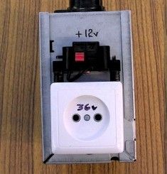
To implement this mode, it is enough to connect the windings 8-8 ', 6-6' and 4-4 'in series and bring the resulting voltage to an external outlet. In the photo it was signed - "36V", and is located on the opposite side from the output, 220-volt outlet side. Now boldly connect your device to it and track the flow of current in the circuits, without fear of touching the live part of the circuit element with your hand.

Additional functions of the isolation transformer

+ 12 volts for checking and tuning car electronics

Another addition is included in the design - the presence of free windings made it possible to integrate a twelve-volt integral stabilizer into the circuit. With it, you can check and configure various automobile and other devices designed for this voltage.

The stabilizer 7812 is turned on as standard and has no features. In the photo below it can be seen below, on the bar of foil fiberglass. The 12 volt output terminals are led above the 36 volt AC outlet, and the +12 volt LED presence indicator is on the top panel of the structure.


For advanced electricians and beginner electronics

The proposed design is extremely simple, but it is able to solve more complex problems. This is a check and repair of devices with switching power supplies, in particular, televisions and switching power supplies of computers.

Checking the operability of the input circuits of switching power supplies using a series-connected incandescent lamp is mentioned above in the article and is described in detail on the Internet pages. I only note that with the help of the design offered to your attention, it is convenient and simple to carry out, without causing difficulties even for a novice repairman.

At the same time, not everyone knows that most switching power supplies are capable of starting from low voltages (no load, of course). Therefore, if you connect the instrument under study to a 36-volt outlet, then with the help of measuring instruments you can verify the serviceability or failure of the start-up unit.

Again, having powered the start-up circuit with a constant voltage of +12 volts from the described device, it is easy to check to check the operation of the generator chip and its strapping, other elements of the circuit. It should be noted that all work is carried out with galvanic isolation from the supply network and with life-safe voltages.

All soldering work, installation of electrical circuits should be carried out with the device disconnected from the mains! This will not only save your health, but also prevent the failure of circuit elements in the event of an accidental circuit.

Nikolay Martov, bgv.electricianexp.com

See also at bgv.electricianexp.com:

  • How to make a safety transformer
  • Home-made step-down transformer for damp rooms
  • The use of transformers in power supplies
  • The electrical circuit of the power supply for the garage
  • Transformers and autotransformers - what is the difference and feature

  •  
     
    Comments:

    # 1 wrote: | [quote]


    Why can't ground the secondary winding? After all, then between the earth having some kind of potential close to zero and the potential on the secondary winding, when it is touched, a significant leakage current will be fatally dangerous to humans. It is necessary to make an independent ground loop in the protected room connected with the secondary winding, but separated from the power supply circuit of the transformer. This system, called "IT", is used, for example, in operating rooms, in addition, it is forbidden to install an RCD in the power supply circuit of the transformer and it is necessary to install a device that controls the insulation resistance of the transformer winding, not to mention the fact that home-made isolation transformers are prohibited in operation.

     
    Comments:

    # 2 wrote: Jacob | [quote]


    Isolation transformer (safety transformer) is a transformer whose primary winding is separated from the secondary windings by protective electrical separation of the circuits, that is, by double or reinforced insulation, or there is a grounded metal protective shield between the windings (paragraphs 1.7.44 and 1.7.49 PUE). Unlike a conventional transformer, the secondary winding of the isolation transformer is not grounded.

    Isolation transformers are used where galvanic isolation of the primary and secondary (load) circuits is required, as well as isolation of the connected equipment from the ground loop. Without isolation, the limiting current flowing between the circuits is limited only by electrical resistances, which are usually relatively small. It is recommended to connect electrical equipment to the network, to increase electrical safety, increase reliability and service life, through an isolation transformer.

    For example, according to the “Electrical Installation Rules”, bathrooms are included in the category of especially dangerous rooms due to the presence of increased humidity, flowing water and an abundance of metal products with unstable grounding. Installation of 220 V sockets is allowed only in a certain area of ​​such rooms, and special measures must be taken to protect against electric shock, in particular, the inclusion of sockets through an isolation transformer is allowed.

    The use of such a connection of the power receiver significantly reduces the likelihood of electric shock, since the currents arising in the event of an insulation breakdown are of little importance, due to the galvanic isolation of the transformer secondary circuits from grounding circuits.

     
    Comments:

    # 3 wrote: Max | [quote]


    In transformerless power supplies with a small constant voltage at the load, with high probability it is possible to get under an alternating voltage of 220 V. In order for this to not happen and galvanic isolation is needed - the absence of electrical contact between the power and the load. I don’t know how relevant this is for power supply, transports are just too powerful, but an isolation transformer is an essential device for setting up electronic equipment!

     
    Comments:

    # 4 wrote: | [quote]


    I did not mean the grounding of the secondary winding of the transformer (error), but the bathroom equipment, since the rules provide for the mandatory performance of additional equalization of potentials, which is galvanically connected with the main equalization, that is, grounding, but according to paragraph 1.7.85 of the PUE and GOST R 50571.3:

    - all cases of power receivers powered from one isolation transformer must be interconnected by a potential equalization conductor that does not have a ground connection (local non-grounded potential equalization system), PE conductors of other circuits and open conductive parts of other circuits;
    - if the connection of electrical receivers is carried out using plug connectors, all plug sockets must have a protective contact connected to a local ungrounded potential equalization system;
    - all flexible cables, with the exception of those supplying Class II equipment, must have a protective conductor used as a conductor of the local non-grounded potential equalization system;
    - measures should be provided for from mechanical and other damage to the circuit conductors powered by the isolation transformer .---------- Although in my opinion this clause contradicts clause 1.7.104 of the same EMP, where grounding calculations are given for networks with isolated neutral, paragraph 2.4.4 of RTM-42 and European standards at the same time. To create an equal potential zone in the environment surrounding a person, it is necessary to provide also a FE-bus of the functional (working) grounding.

     
    Comments:

    # 5 wrote: Ruslan | [quote]


    Thanks!

     
    Comments:

    # 6 wrote: | [quote]


    Thank you for the article! I have a question. Can an isolation transformer replace a voltage regulator? For example, for a gas boiler.

    Can he cope with voltage drops? Or does he use it only for protective purposes?

    Thanks!

    Paul.

     
    Comments:

    # 7 wrote: andy78 | [quote]


    No, he can not. The isolation transformer has a different purpose. Read the article again.

     
    Comments:

    # 8 wrote: | [quote]


    Tell me, why, if the isolation transformer is so good, they are not placed in transformer booths at the entrances to houses, but they feed us with a dangerous phase with zero?

     
    Comments:

    # 9 wrote: petruchito | [quote]


    36 volts with such a switching circuit will be on one side of the screen with the network (when the network is connected at 5-15 and 5'-15 '), with a breakdown of insulation it can also kill ...

     
    Comments:

    # 10 wrote: | [quote]


    “when the TV was turned on, the lamp came on with a steady light - a short circuit in the power cord, in the input circuits of the power supply” - but should the fuse in the secondary circuit not burn out during a short circuit, and then the lamp will not light? Maybe the lamp should be in the secondary circuit?

     
    Comments:

    # 11 wrote: | [quote]


    Hello everybody. In a transformer booth, zero is still connected to the earth in the old fashioned way, out of habit. One hundred years ago, as some kind of smart person came up with this, they still do it here, they say that it’s for protection against electric shock.But in reality there is no protection !!! This is because the neutral wire connected to the ground is already connected to the person - the person is walking on the ground ... and it is worth touching the person by chance to another wire, called the "phase", it beats with current. Why does it strike at 220 volts? At high voltage, a high current passes through our body, and at low voltage, the current is weak. At 36 volts, a very small current passes through our body, a few milliamps. We may not even feel such a current. At a voltage of 220 volts, a current of much larger magnitude, several tens of milliamps, can already pass through our body. A current of 50 milliamps for a person is already dangerous, and 100 milliamps is deadly. Of course, there are different cases - if in a dry apartment a person stands on a dry floor, then he will not be shocked too much. But God forbid people to stand on damp earth and touch the wire "phase" - this is death.

    I want to tell you why in those not very distant times, 100 years for history is nothing at all, they proposed and approved to connect the zero wire to the "ground". Electricity then only began to enter into the life of ordinary people. All this was very expensive, including wires from the power plant to the consumer. For an incandescent bulb, two wires must be brought in - zero and phase. So they decided to make one wire thinner, zero and connect it also to the ground. And then part of the current will pass through the earth, and part through the zero wire. Grounding was placed near almost every post and near the consumer's house. Everything turned out to be seemingly good. A thinner wire needed less metal. Non-ferrous metallurgy was then not very "advanced". Everything was very expensive. This is only later, when many modern power plants were set up and non-ferrous metals were smelted in electrolysis furnaces, metals became cheaper, including aluminum from which linear wires are made. Although the wires became cheaper, but still the neutral wire was still grounded and many thousands of people have already died from this grounded zero !!!! Abroad, they have long abandoned the grounded zero. There they conduct another third ground wire, really to protect human life. That's it.

    Now I’ll also say why it’s advisable to have at least a 200–250 watt isolating transformer in the house, especially in the bathroom. Now we use many electric appliances in the bathroom as well: we blow dry our hair with a hairdryer, and we can put a small boiler into a glass. In the isolation transformer, it is no longer necessary to connect the zero of the secondary winding to the ground. The isolation transformer also serves to disconnect a zero from the earth. With such a connection of the wires of the secondary winding, we will not be shocked, even if we take on the phase wire of the secondary winding of the isolation transformer. This is because there will be no closed circuit between the zero of the separation transformer and the person. And do not listen to the current clever specialists, that it is necessary to ground zero in the bathroom. Only electrical enclosures need to be earthed !!! And in no case do you need to connect your zero to the body in electrical installations !!! Good luck to you all. Use electricity. It is very comfortable.

    As a child, I watched how we did street wiring with us and it was very surprising to me that the electric wire was screwed to the exposed pipe of the gander riser. I knew then that it was impossible to touch electric wires, I knew how it nipped. Then, later I found out that this is a zero wire and it does not “beat”. And yet I still wonder how we relate to human life. It seems that everything is strictly safety precautions. At work, we sign for safety precautions that we are familiar with and strictly abide by the truth, and people die from electric shock. During my life, two people died at work with me.After the army, I worked at Selkhoztekhnika, where a tractor driver wanted to close the hood hatch in the winter and took hold of the electric lift box, and there he exposed three phases and killed him. Then I went to work in the city, there killed ELECTRICIAN. He was repairing an electric drive opening the gate there. If there were no grounded zero, people would not have died !!! And everything according to the rules, everything according to the instructions ... Why, then, do people die. So our instructions are not suitable !!! Urgent need to remove the grounded "ZERO"!

     
    Comments:

    # 12 wrote: | [quote]


    Incorrectly connected pins. This connection will not work, because the windings towards each other. The correct arrangement of the terminals of the primary 1-2 and 15'-5 ', and the secondary 2'-1' and 5-15

     
    Comments:

    # 13 wrote: Valery | [quote]


    And I would not engage in amateur performances in the manufacture of such a vital device as an isolation transformer. Still, this is not the time of a general deficit. In any city there are specialized electrical shops where you can buy an industrially manufactured isolation transformer with guaranteed and proven electrical insulation properties. In addition, they are soaked, unlike television and are not afraid of high humidity. Life - it, brothers, is more expensive than any money!

     
    Comments:

    # 14 wrote: | [quote]


    Hello! Bought a transformer.

    When connected to the network WITHOUT LOAD, it knocks out the machine. Why???

    Opened.

    Transformer "power" wire is three-wire. Zero, phase - clearly go to the primary winding (one of them through a fuse).

    The ground wire is screwed to the metal casing and the ground contact of the load power socket.

    - I measured the resistance of the windings - the same (I do not remember exactly, something about 3 Ohms), the difference in hundredths.

    - “Rang” the power plug: “phase” - “ground”, “zero” - “ground. Do not“ ring ”.

    - I did the same with the outlet for connecting the load. Everything is fine.

    - He took out the fuse (i.e. disconnected one end of the winding) - the machine does not knock out. So the wire is normal, it won’t be somewhere "inside of itself".

    Why can an automatic machine be knocked out idling? Shorty in the primary? But the resistance of the windings is the same and not 0.03 or 0.3 Ohm, which would be short.

    By the way, the rubber legs on the bottom and the cover of the case are mounted ON THE TAPPERS, WHICH STOOR INSIDE and wires lie on them !!!

    It is clear that the probability of cutting the sheath of wires through the sharp ends of the self-tapping screws is small, but as a fact of the "production culture" it is obvious. Screws "C grade" there would be more out of place.

    And a socket for connecting the load - you look for such a plug. No, French teapots with a hole. And yet, I somehow never met other electrical appliances with such a plug.

    Dmitriy,

    The transformer is this: ... w.220-110.rf / product / ts220220-1500 /

    Not an advertisement. It’s just that I’m not asking about “transformer in general” or some kind of homemade product.

     
    Comments:

    # 15 wrote: | [quote]


    Two electricians are sitting on a pole. Grandma is walking by. Electrician: granny .. let that wire lie on the ground .. Granny filed and went on. The first electrician to the second: I said "earth" ... and you - phase, phase ...

     
    Comments:

    # 16 wrote: | [quote]


    and why the light bulb in the primary circuit 220, and not in the secondary?
    After all, the device under test will be connected to the secondary, it will take the short-circuit current from the secondary, we must protect the secondary, otherwise the secondary will be burned out by a faulty PSU. But in the pepper, insert the fuse and indicator lamp.

     
    Comments:

    # 17 wrote: Paul | [quote]


    The essence of using an isolation transformer is to completely separate the receiver circuit from the power supply. This is an additional protection that does not relieve you of the obligation to exercise special caution and meaningfulness. Direct contact with devices powered by an isolation transformer (or IT network) is not 100% safe.It should also be remembered that after the isolation transformer, we do not distinguish between “L” and “N” - we have two “L”. Isolation transformers (with appropriate power) are the main element of the kits supplying power to the isolated “IT” power supply network. Some isolation transformers have a shield between the windings, which is supposed to replace the inner capacitance of the transformer with a smaller capacity on a straight surface, thereby reducing transformer leakage (through the longitudinal reactance). Such transformers are recommended for hospitals and as elements that provide protection against interference in recording studios, directors and laboratory measuring stands.