Categories: Featured Articles » Practical Electronics
Number of views: 276,201
Comments on the article: 14

How to make a power supply from an electronic transformer
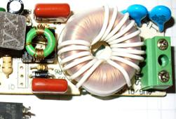
 

How to make a power supply from an electronic transformer?After all that has been said in the previous article (see How is an electronic transformer arranged?), it seems that making a switching power supply from an electronic transformer is quite simple: put a rectifier bridge on the output, smoothing capacitor, if necessary, a voltage regulator and connect the load. However, this is not quite true.

The fact is that the converter does not start without load or the load is not sufficient: if you connect an LED to the rectifier output, of course, with a limiting resistor, you will be able to see only one flash of the LED when it is turned on.

To see another flash, you will need to turn off and on the converter to the network. In order for the flash to turn into a constant glow, you need to connect an additional load to the rectifier, which will simply select the useful power, turning it into heat. Therefore, such a scheme is used when the load is constant, for example, a DC motor or an electromagnet, which can only be controlled by the primary circuit.

If the load requires a voltage of more than 12V, which is produced by electronic transformers, it will be necessary to rewind the output transformer, although there is a less time-consuming option.


An option of manufacturing a switching power supply without disassembling an electronic transformer

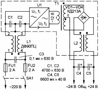
A diagram of such a power supply is shown in Figure 1.

Bipolar power supply for amplifier

Figure 1. Bipolar power supply for the amplifier

The power supply is made on the basis of an electronic transformer with a power of 105W. To manufacture such a power supply unit, it will be necessary to manufacture several additional elements: a line filter, a matching transformer T1, an output choke L2, rectifier bridge VD1-VD4.

The power supply has been operating for several years with a ULF power of 2x20W without complaints. With a rated mains voltage of 220V and a load current of 0.1A, the output voltage of the unit is 2x25V, and when the current is increased to 2A, the voltage drops to 2x20V, which is quite enough for the normal operation of the amplifier.

Matching transformer T1 is made on a ring K30x18x7 from ferrite grade M2000NM. The primary winding contains 10 turns of PEV-2 wire with a diameter of 0.8 mm, folded in half and twisted with a bundle. The secondary winding contains 2x22 turns with a midpoint, the same wire, also folded in half. To make the winding symmetrical, you should wind it in two wires at once - a bundle. After the winding, to obtain the midpoint, connect the beginning of one winding with the end of the other.

You will also have to make an L2 inductor yourself; to manufacture it, you need the same ferrite ring as for the T1 transformer. Both windings are wound with PEV-2 wire with a diameter of 0.8 mm and contain 10 turns.

The rectifier bridge is assembled on KD213 diodes, you can also use KD2997 or imported, it is only important that the diodes are designed for an operating frequency of at least 100 kHz. If instead of them you put, for example, KD242, then they will only warm up, and you won’t be able to get the required voltage from them. Diodes should be installed on a radiator with an area of ​​at least 60 - 70cm2, using insulating mica pads.

Electrolytic capacitors C4, C5 are composed of three parallel-connected capacitors with a capacity of 2200 microfarads each. This is usually done in all switching power supplies in order to reduce the overall inductance of electrolytic capacitors. In addition, it is also useful in parallel to install ceramic capacitors with a capacity of 0.33 - 0.5 μF, which will smooth out high-frequency oscillations.

It is useful to install an input line filter at the input of the power supply, although it will work without it.As an input filter inductor, a ready-made DF50GTs inductor used in 3USTST TVs was used.

All units of the block are mounted on a board of insulating material by hinged mounting, using the findings of the parts for this. The entire structure should be placed in a shielding housing made of brass or sheet metal, with cooling holes provided in it.

A properly assembled power supply does not need adjustment, it starts working immediately. Although, before putting the block in the finished structure, you should check it. For this, a load is connected to the output of the unit - resistors with a resistance of 240 Ohms, with a power of at least 5 watts. Turning the unit on without load is not recommended.


Another way to refine the electronic transformer

There are situations that you want to use a similar switching power supply, but the load is very "harmful". The current consumption is either very small or varies widely, and the power supply does not start.

A similar situation arose when they tried in a lamp or chandelier with built-in electronic transformers, instead halogen lamps to put LED. The chandelier simply refused to work with them. What to do in this case, how to make it all work?

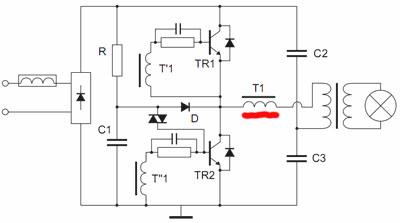
To deal with this issue, let's look at Figure 2, which shows a simplified diagram of an electronic transformer.

Simplified electronic transformer circuit

Figure 2. Simplified diagram of an electronic transformer

Pay attention to the winding of the control transformer T1, underlined by a red stripe. This winding provides current feedback: if there is no current through the load, or it is just small, then the transformer simply does not start. Some citizens who bought this device connect a 2.5W light bulb to it, and then carry it back to the store, they say, it does not work.

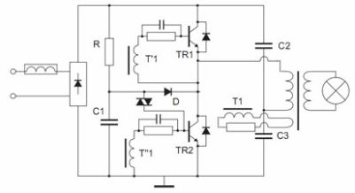
And yet, in a fairly simple way, you can not only make the device work almost without load, but also make it short-circuit proof. A method for such a refinement is shown in Figure 3.

Finalization of the electronic transformer. Simplified scheme

Figure 3. Refinement of the electronic transformer. Simplified scheme.

In order for the electronic transformer to work without a load or with a minimum load, the current feedback should be replaced by voltage feedback. To do this, remove the current feedback winding (underlined in red in Figure 2), and instead solder the wire jumper into the board, naturally, in addition to the ferrite ring.

Further on the control transformer Tr1, this is the one that, on a small ring, wraps a winding of 2 - 3 turns. And there is one turn on the output transformer, and then the resulting additional windings are connected, as indicated in the diagram. If the converter does not start, then you need to change the phasing of one of the windings.

The resistor in the feedback circuit is selected within the range of 3-10Ohm, with a power of at least 1W. It determines the depth of feedback, which determines the current at which the generation will fail. Actually this is the fault current protection. The greater the resistance of this resistor, the lower the load current the generation will fail, i.e. operation of protection against short circuit.

Of all these improvements, this is perhaps the best. But this does not hurt to supplement it with another transformer as in the diagram according to Figure 1.

Boris Aladyshkin

See also at bgv.electricianexp.com:

  • How is an electronic transformer
  • The electrical circuit of the power supply for the garage
  • Simple emergency light source
  • How to determine unknown transformer parameters
  • How to power a cordless screwdriver from an electrical network

  •  
     
    Comments:

    # 1 wrote: | [quote]


    Great helpful article.

     
    Comments:

    # 2 wrote: | [quote]


    Dear Boris.
    Transformer EK105S, manufacturer of LIGHT (FOSHAN GEDI ELEKTRONIK CO.LTD)
    Situation: when a load is connected to the output of an electric transformer even with a slight inductance - (the wire is rolled 3-4 turns into a ring without a core) the unit does not start. I need to load ElTr with a boost trance.
    Sincerely, Valery Nikitovich.

     
    Comments:

    # 3 wrote: | [quote]


    why and why are the base resistors and collector-emitter of transistors shunted?

     
    Comments:

    # 4 wrote: | [quote]


    Thanks for the article, now I’m just working on finalizing my trance, only I have Camellion. However, it would be useful to supplement the article with a graph of the dependence of the limiting current on the resistance in the feedback circuit, at least for ideal conditions. All the same, not everyone has the necessary knowledge to calculate it, but their hands itch, experimental selection at the same time can end with fireworks. The price of the issue is a penny, but still I would like to rely on more or less accurate data during the alteration.

     
    Comments:

    # 5 wrote: | [quote]


    After such a refinement (Feron 200 W transformer), the circuit still does not start with a small load. But the most unpleasant "surprise" appeared in the fact that with the 5 (!) - watt lamp the output transistors did not start to warm up childishly. Explain if it does not bother you. By the way, instead of a resistor, a 0.22 μF capacitor was used in the feedback winding.

     
    Comments:

    # 6 wrote: Boris Aladyshkin | [quote]


    Muchitel, it is easiest to assemble a similar circuit using an output transformer from the same unit: the secondary winding is connected to the output of the electronic transformer, and the primary (now it will be secondary) is used at its discretion. Rewinding may be required if necessary. The output, of course, must be connected to the load. People made such circuits, there were no problems with starting due to inductance.

    DimaThese are standard circuit solutions. The base resistors are shunted by the so-called accelerating capacitors. Due to them, transistors turn on faster, the steepness of the edges of the output pulses increases, so the transistors heat up less actively. The collector - emitter is shunted by diodes connected in the opposite direction. Their purpose is to protect transistors from EMF emissions of self-induction when the transistors are turned off. For this purpose, there are special protective diodes - suppressors, which are distinguished by a high frequency and normalized operating voltage. Instead, it is quite possible to use rectifier diodes designed to operate at high frequencies, for example, KD226G.

    Vladislav, Feron transformers are most suitable for such alterations, since the output transformer is wound on a ring. At Tashibra, for example, the core of this transformer is W-shaped, it can only be split.

    Why may not start. The case with improper phasing of the windings will not be considered, although this should not be forgotten. If the rectifier is installed at the output in a bridge circuit with a large capacitor, it may not start. In this case, switching on after the inductor bridge with an inductance of about 50 microgenry will help. Such a choke will turn out if 25 turns of PEL 1.2 wire are wound on a 27 * 14 * 12 ferrite core (this can be removed from an old computer PSU). You can also use a bundle of 2 ... 3 folded together wires of a smaller diameter.

    Why can it get warm. Between the feedback windings, a resistor is usually installed, better than 2 connected in parallel 6.8 Ohms of 5 watts, which will be 3.4 Ohms. The magnitude of these resistors is regulated within certain limits: without load it should be 30KHz, and under load the frequency will increase.

    A 0.22μF capacitor at a frequency of 30 KHz has a reactance of 24 Ohms. Try first with resistors, pick up the resistance at which it will work normally, and then replace it with a capacitor of a suitable capacity. Very good results are obtained when replacing standard transistors with mosfets, for example, IRF840. With such a rework, the unit works much more stable.

     
    Comments:

    # 7 wrote: | [quote]


    Dear Boris, thank you for answering. I don’t know why they write that Tashibrovsky trances have a U-shaped core. I have two 60 watts each in plastic and metal — both have rings. But this is between the case.There is no capacitor at the output of the Feron bridge, with a lamp of 40 W or more it starts up, and the greater the load, the less the heating of transistors (?). I put a 2 W resistor on the winding of the OS, a little warm, I will leave it. And last, is it so simple to set field instead of bipolar? They have a different management method and the principle of work, too. Maybe at least pick up the resistors in the gate circuit? Did you do that yourself? Forgive me for taking your time, could you give a link to the site, if you have one, where there would be a transformer circuit on the field, and that with a wiring of 300 watts. Again, the control trance is not needed there. Regards, Vladislav.

     
    Comments:

    # 8 wrote: | [quote]


    FERON TRA 110 / 200W. People, did everything as shown in the diagram, with the exception of adding a capacitor after d / bridge to 220 uF x 400 V to smooth out ripples, after 10 seconds one of the resistors on the board blazed with a bang ... PPC ... I checked it all 10 times , consistent with the scheme, before the alteration trans was working. Turned off, discharged the capacitor, I touch the transistors - all 4 boiling water! Is it really because of the voltage of 400 volts after the capacitor ??? Your opinion...

     
    Comments:

    # 9 wrote: | [quote]


    What are you bothering with - in our energy sector, power supplies for LED strips cost no more than 200 rubles.

     
    Comments:

    # 10 wrote: | [quote]


    U menia dva meshka plati ot energosberegaiushih 80 watnih lamp.shemi identichni god muchalsia shtob zastavit rabotat na nizkuiu nagruzku. Bolshoe ogromnoe spasibo za statiu ....

     
    Comments:

    # 11 wrote: | [quote]


    Good afternoon! Redid ET (150W). Winding current OS removed. 1 turn (OS by voltage) is wound on a switching trance and 2 - on a power one. Transons are connected through a 3.4 ohm resistor. The rectifier bridge and the conductors at the output of the ET have not yet been hung. ET starts up, but when you try to connect the load (21W auto lamp), as I understand it, it goes into defense and does not return until you restart it. The direction of the turns, the diameter of the wire ext. windings and the value of the resistor changed in both directions - nothing changes. What could be the reason?

     
    Comments:

    # 12 wrote: | [quote]


    And if instead of reworking to the output winding, just add a metal-film capacitor, in parallel. How will it work? In theory, it will create short-term surges during recharging, this is enough for the generator to work. Will there be a bias?

     
    Comments:

    # 13 wrote: | [quote]


    To Alexander. Well, you thought of it, 220mkf set this current. 3-4 microfarads is enough.

     
    Comments:

    # 14 wrote: Mechanic Green | [quote]


    Your one-watt resistor between the control and output transformers will warm up, like a fart circuitry from this article. Why aren't you using capacitance?