Categories: Practical Electronics, How does it work
Number of views: 252103
Comments on the article: 21

How is an electronic transformer
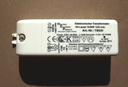
 

How is an electronic transformer arranged?Externally electronic transformer It is a small metal, usually aluminum case, the halves of which are fastened with just two rivets. However, some companies produce similar devices in plastic cases.

To see what is inside, these rivets can simply be drilled. The same operation will have to be done if an alteration or repair of the device itself is planned. Although at its low price it is much easier to go and buy something else than to repair the old. Nevertheless, there were many enthusiasts who not only managed to figure out the device design, but also developed several switching power supplies.

The circuit diagram for the device is not attached, as well as for all current electronic devices. But the circuit is quite simple, contains a small number of parts, and therefore the circuit diagram of an electronic transformer can be copied from a printed circuit board.

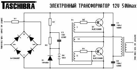
Figure 1 shows a similarly drawn Taschibra transformer circuit. Converters manufactured by Feron have a very similar circuit. The only difference is in the design of printed circuit boards and the types of parts used, mainly transformers: in Feron converters, the output transformer is made on a ring, while in Taschibra converters on a W-shaped core.

In both cases, the cores are made of ferrite. It should be noted right away that ring-shaped transformers with various modifications of the device are easier to rewind than W-shaped ones. Therefore, if an electronic transformer is purchased for experiments and alterations, it is better to buy a Feron device.


When using an electronic transformer for power only halogen lamps the name of the manufacturer does not matter. The only thing you should pay attention to is power: electronic transformers are available with a power of 60 - 250 watts.

Taschibra Electronic Transformer Circuit

Figure 1. Taschibra electronic transformer circuit

A brief description of the electronic transformer circuit, its advantages and disadvantages

As can be seen from the figure, the device is a push-pull oscillator made according to a half-bridge circuit. Two shoulder bridge made on transistors Q1 and Q2, and the other two arms contain capacitors C1 and C2, so this bridge is called a half-bridge.

Mains voltage rectified by a diode bridge is supplied to one of its diagonals, and the load is included in the other. In this case, this is the primary winding of the output transformer. According to a very similar scheme electronic ballasts for energy-saving lampsbut instead of a transformer, they include a choke, capacitors and filament of fluorescent lamps.

For management transistor operation windings I and II of the T1 feedback transformer are included in their base circuits. Winding III is current feedback, through which the primary winding of the output transformer is connected.

The control transformer T1 is wound on a ferrite ring with an external diameter of 8 mm. Basic windings I and II contain 3..4 turns each, and feedback winding III - only one turn. All three windings are made of wires in multi-colored plastic insulation, which is important when experimenting with the device.

On the elements R2, R3, C4, D5, D6, the startup circuit of the autogenerator is assembled at the time the entire device is connected to the network. Rectified input diode bridge mains voltage through resistor R2 charges capacitor C4. When the voltage on it exceeds the threshold of operation of the dynistor D6, the latter opens and a current pulse is generated on the basis of transistor Q2, which starts the converter.

Further work is carried out without the participation of the launch chain.It should be noted that the D6 dinistor is double-sided, can operate in AC circuits, in the case of direct current, the polarity of the inclusion does not matter. On the Internet, it is also called "diac."

The network rectifier is made on four diodes of the type 1N4007, the resistor R1 with a resistance of 1Ω and a power of 0, 125W is used as a fuse.

The converter circuit, as it is, is quite simple and does not contain any "excesses". After the rectifier bridge, not even a simple capacitor is provided for smoothing the ripples of the rectified mains voltage.

The output voltage directly from the output winding of the transformer is also supplied without any filters directly to the load. Are absent output voltage stabilization circuit and protection, therefore, during a short circuit in the load circuit several elements burn out at once, as a rule, these are transistors Q1, Q2, resistors R4, R5, R1. Well, maybe not all at once, but at least one transistor for sure.

And despite this seemingly imperfection, the circuit fully justifies itself when used in the normal mode, i.e. to power halogen lamps. The simplicity of the circuit determines its cheapness and widespread use of the device as a whole.


Study of the operation of electronic transformers

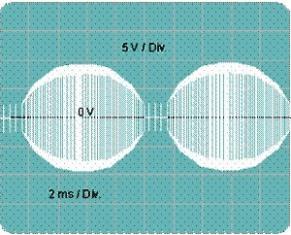
If a load is connected to an electronic transformer, for example, a 12V x 50W halogen lamp, and an oscilloscope is connected to this load, then on its screen you can see the picture shown in Figure 2.
Oscillogram of the output voltage of the Taschibra 12Vx50W electronic transformer

Figure 2. Oscillogram of the output voltage of the Taschibra 12Vx50W electronic transformer

The output voltage is a high-frequency oscillation with a frequency of 40 KHz, modulated at 100% frequency of 100 Hz, obtained after rectification of the mains voltage with a frequency of 50 Hz, which is quite suitable for supplying halogen lamps. Exactly the same picture will be obtained for converters of another power or another company, because the circuits practically do not differ from each other.

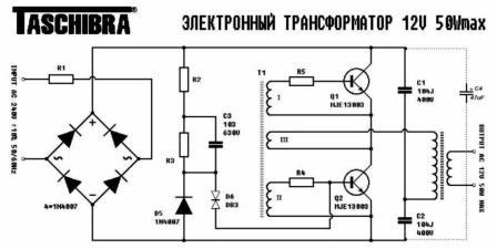
If connected to the output of the rectifier bridge electrolytic capacitor C4 47uFx400V, as shown by the dashed line in Figure 4, the load voltage will take the form shown in Figure 4.

Connecting a capacitor to the output of the rectifier bridge
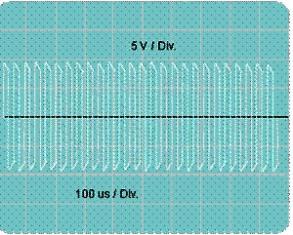
Figure 3. Connecting a capacitor to the output of the rectifier bridge

Converter output voltage after connecting capacitor C5

Figure 4. Voltage at the converter output after connecting the capacitor C5

However, we should not forget that the charging current of the additionally connected capacitor C4 will lead to the burnout, rather noisy, of the resistor R1, which is used as a fuse. Therefore, this resistor should be replaced with a more powerful resistor with nominal values ​​of 22 Ohm2W, the purpose of which is simply to limit the charging current of capacitor C4. As a fuse, you should use a conventional 0.5A fuse.

It is easy to notice that the modulation with a frequency of 100 Hz has stopped, only high-frequency oscillations with a frequency of about 40 KHz remain. Even if there is no way to use an oscilloscope in this study, this indisputable fact can be noticed by a slight increase in the brightness of the bulb.

This suggests that the electronic transformer is quite suitable for creating simple switching power supplies. There are several options: using the converter without disassembling, only by adding external elements and with small changes to the circuit, very small, but giving the converter completely different properties. But we will talk about this in more detail in the next article.

Boris Aladyshkin

Continuation of this topic: How to make a power supply from an electronic transformer

See also at bgv.electricianexp.com:

  • Electronic Transformers: Purpose and Typical Use
  • How to make a power supply from an electronic transformer
  • What is the difference between the power supply for LED lamps and electronic transformer ...
  • Simple emergency light source
  • Transistor Test Probe

  •  
     
    Comments:

    # 1 wrote: | [quote]


    Sorry, but the accuracy of the presentation in this article is clearly bad.The numbers of elements and figures are confused, which interferes with reading. In general, I like the very trend of covering various applied knowledge on your site. I get a lot of necessary information. Thanks.

     
    Comments:

    # 2 wrote: | [quote]


    Thanks for the information. I would like more information about new developments in electrical engineering.

     
    Comments:

    # 3 wrote: | [quote]


    Usually people think that the name of the manufacturer is important anytime, anywhere. I will never advise my customers to buy the same transformers for sub-collection or unknown companies, and if possible Osram, Philips, Mean Well.

     
    Comments:

    # 4 wrote: | [quote]


    Thank you for the information, helped in the repair.

     
    Comments:

    # 5 wrote: | [quote]


    Can this transformer be used to power LED lamps? Maybe you need an additional rectifier in the form of a bridge and a capacitor?

    Can this transformer be used for filament nichrome filament for cutting foam?

     
    Comments:

    # 6 wrote: Evgeny | [quote]


    Yes you can. An electronic transformer works well with any active load - lamps, resistances, heating elements.

     
    Comments:

    # 7 wrote: | [quote]


    Boris, You are well done. You are accessible and popularly present information for electricians who want to delve into electronics. Now it’s getting closer. Your articles give people the opportunity to understand the ongoing processes in electronic components.

    elalex, and now these companies are faking. If it is possible to open the product before purchase, it will immediately be visible.

     
    Comments:

    # 8 wrote: | [quote]


    Thanks for the information!!! For LED lamps it is better not to use it! (for a long time they will not be enough). Since at the input they have a diode bridge of low-frequency diodes up to 1000 Hz !!!! At a frequency of 40000 Hz they are very hot + voltage loss from the bridge and low load on the transformer !!!! It is better to use a stub. a source for LED strips with a constant stabilized voltage of 12V + protection for current and short circuit, etc. There are airtight baths. Drivers Navigator ND series for LED lamps and modules ND-P-IP67 power supply DR-75W manufactured by Brille, a lower power type DR-15W, Electronic Light CS 31350M - for connecting a point LED lamp or low-power LED strip (up to 10 W).

     
    Comments:

    # 9 wrote: slonspb | [quote]


    --Since at the entrance they have a diode bridge of low-frequency diodes up to 1000Hz !!!!

    at 50Hz input, electric hr_nov ...
    Feng Shui fans can buy a laboratory PSU for $ 10,000 and enjoy)

     
    Comments:

    # 10 wrote: mmmnt | [quote]


    The output voltage is a high-frequency oscillations with a frequency of 40 KHz, modulated at 100% frequency of 100 Hz - in my opinion the previous speaker is right, 40 KHz, according to the attached information, no?

     
    Comments:

    # 11 wrote: Primus | [quote]


    slonspb, It’s not worth calling another one a shitty electrician to someone who’s not kicking in electronics. Comrade had in mind that at the entrance of any energy-saving device there are ordinary low-frequency diodes designed to operate at a low frequency. If you apply a variable with a frequency of 40 kHz to the input of such a rectifier, then the diode will not have time to close, a through current will flow through it, which will lead to a short circuit.

    Learn better materiel, instead of teaching others. Sometimes it's better to chew than talk.

     
    Comments:

    # 12 wrote: | [quote]


    A beginner's question in electronics. What is the advantage of this circuit, changing the input frequency on the power supply from 50Hz to 40KHz at the output to the consumer. Why change the output voltage frequency so much?

     
    Comments:

    # 13 wrote: | [quote]


    robin, I'm not a pro, but I know that at a high frequency the efficiency of transformers is much higher. This allows you to make lightweight power supplies (PSUs). Compare the weight and dimensions of modern pulse PSUs with old PSUs in which there were kilogram transformers. Those. It turns out a huge saving of planet resources.

    I forgot to write that in ordinary pulsed PSUs, a constant current with small ripples is output to the consumer. And the fact that in this "electronic transformer" 40 kHz is output, means for those applications for which it is designed, it will do.

     
    Comments:

    # 14 wrote: | [quote]


    Quote: Eugene
    Yes you can. The electronic transformer works well with any active load - lamps, resistances, heating elements

    Question on power consumption. There is a Taschibra 105 W loaded with 4 diode lamps of 7 watts each. What is the total power consumption?

     
    Comments:

    # 15 wrote: | [quote]


    I connected 12v LED lamps in the bathroom and one halogen lamp to one transformer for halogen lamps. All types of lamps work together and simultaneously from this transformer. Question: why do LED lamps work, because they need special transformers and everywhere it is mentioned.
    Question 2: as far as I understand, the secondary current from this transformer is also alternating, and the LED lamps are designed for direct current, why do they work (by the way, these same lamps also work from the DC adapter for 12V)
    Question 3: Everywhere it is mentioned that for the operation of LED lamps it is necessary to observe the polarity, otherwise it will not work, or it may burn out if the reverse half-period of the voltage exceeds the permissible lamp rating, but the aforementioned LED lamps work at any polarity of direct current. How so?

     
    Comments:

    # 16 wrote: Vladimir | [quote]


    LED is the same diode. It rectifies alternating current and at the same time glows. But LEDs have a low reverse voltage of 5 volts, this should be remembered. In principle, you can immediately connect the cd tape to the output of the electronic transformer and will work. In the tape 3 c-d in series, that is, the reverse voltage is 15 volts.

     
    Comments:

    # 17 wrote: | [quote]


    Maybe you can poke my nose ... Where is C4 ??? You write everything about him, but he is not on the diagram !!!

     
    Comments:

    # 18 wrote: | [quote]


    Michael,
    Your Bear ..... take off your glasses.

     
    Comments:

    # 19 wrote: Yuri | [quote]


    Tell me, can I connect a 12-volt LED car lamp through Feron ET 60 (12 V)?

     
    Comments:

    # 20 wrote: Oleg | [quote]


    Quote: dimedrol
    robin, I'm not a pro, but I know that at a high frequency the efficiency of transformers is much higher. This allows you to make lightweight power supplies (PSUs). Compare the weight and dimensions of modern pulse PSUs with old PSUs in which there were kilogram transformers. Those. It turns out a huge saving of planet resources. I forgot to write that in ordinary pulsed PSUs, a constant current with small ripples is output to the consumer. And the fact that in this "electronic transformer" 40 kHz is output, means for those applications for which it is designed, it will do.

    Not at all!

    In low-frequency el. machines (transformer with laden iron) as well as high-frequency (on a ferrite core) efficiency is close to 90%. And the dimensions and weight are smaller due to the fact that at a high frequency for transmitting the same power as at low, a smaller cross section of the winding wires is required and, due to other magnetic properties of the core (ferrite), fewer turns and smaller dimensions of the cross section of the core itself. Ultimately, due to losses in the generation of high frequency, the resulting efficiency of the pulsed PSU will be less. However, even in spite of this and the complexity of the circuit, they have really smaller dimensions.

    And the fact that the output voltage of the impulniks is constant, only indicates the presence of an output diode rectifier (bridge, or a pair of diodes) in it. And the ripple is due to the quality of the output filter (capacitors and chokes).

    If the Schottky diode bridge and the corresponding filters are added to the output of the "electronic transformer", then we get a quite normal pulse generator with a constant output. Only without stabilization, since there is no feedback.

    As for active consumers (incandescent lamps and other heating elements), they generally do not care what to eat (by switching, constant, pulses), the main thing is not to exceed the voltage limit so as not to overheat.

     
    Comments:

    # 21 wrote: Gregory d27xpf | [quote]


    Others who have at least a Feron TRA110 250 (200) board drawing. Throw off