Categories: Featured Articles » Practical Electronics
Number of views: 79375
Comments on the article: 6
Electronic thermostat for oil cooler
 An article on how to replace a mechanical temperature regulator of an oil heating radiator.
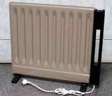
Quite often in everyday life you have to use oil radiators for heating. As a rule, such days come in the fall, when it is already quite cold outside, and public utilities are in no hurry to turn on central heating in apartments. These radiators do not burn air oxygen, unlike other types of heating electric appliances.
The heating temperature for such radiators is set using an electromechanical regulator, the basis of which is a bimetallic plate - it controls the operation of the mechanical contact. This contact switches off the heater when the set temperature is reached.
When such a regulator becomes unusable, it cannot be repaired in almost a hundred percent of cases. It becomes impossible to use a radiator without a temperature controller: either you need to manually turn it on periodically - turn it off, or sit and wait for a fire to happen. The semiconductor temperature controller described in this article will help get rid of this situation.
Semiconductor Temperature Sensors
A distinctive feature of this controller is that it does not require temperature calibration, since it uses the LM335AZ sensor, calibrated already at its manufacture by the manufacturer.
There are several types of calibrated temperature sensors, for example DS1621, DS1820 and some others. These sensors provide temperature readings in digital form, so the measurement result is only available microcontroller devicesthat require programming.
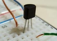
Analog temperature sensor LM335AZ
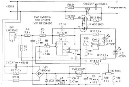
The LM335AZ sensor provides the measurement result in analog form (voltage), which does not require the use of microcontrollers and writing programs. It is enough to assemble a simple circuit and the device will work as intended. The scheme of the described temperature controller is shown in Figure 1.

Figure 1. Thermostat for the oil cooler.
According to the principle of operation, the LM335AZ is one of the varieties of a semiconductor controlled zener diode, the stabilization voltage of which depends on the ambient temperature. This characteristic is strictly standardized and amounts to 10 mV / ° C. In this case, the temperature coefficient of voltage (TKN) is positive, that is, with an increase in temperature by each degree, the voltage at the output of such a sensor increases by 10 mV.
The manufacturer guarantees that when the temperature changes within -40 ... + 100 ° C, the characteristic of the sensor is linear, and the error is not more than ± 1 ° C. Such accuracy is quite enough to control the temperature of the heater. It should be noted separately that such parameters will be achieved at a current through the zener diode at a level of 0.45 ... 5.0 mA.
 LM335AZ sensors are calibrated on Kelvin temperature scale. To transfer the temperature from the degrees of Celsius familiar to us all, we will have to use the following formula: t ° K = 273 + t ° C. Given the aforementioned temperature coefficient of the sensor 10 mV / ° C, the voltage in millivolts at its output will be ten times higher than the readings in degrees.
A simple example: if in our room the wall thermometer shows 25 degrees, then the voltage at the output of the LM335AZ sensor will be (273 + 25) * 10 = 2980 mV or 2.98 V. It is easy to calculate that if the oil cooler is heated to 70 ° C the voltage at the output of the LM335AZ sensor will be (273 + 70) * 10 = 3430 mV or 3.43 V. It turns out that to create a thermostat you just need to measure the voltage at the output of the sensor and compare it with the reference voltage, which sets the heating temperature.
After such a detailed consideration of the sensor, we can proceed to the description of the circuit diagram of the thermostat, which contains a small number of parts, is simple to manufacture, and almost does not require adjustment.
Thermostat power supply
The power supply for the temperature controller is assembled according to the well-known scheme with a quenching capacitor. In the diagram, this is C1. In parallel, a resistor R1 is installed through which the above capacitor will be discharged after disconnecting the device from the network.
Most of all, this discharge is needed when setting up and manufacturing a temperature regulator, - you must agree that it is not very pleasant to receive electric shocks, clutching a capacitor charged to the mains voltage for forgetfulness.
Resistor R2 reduces the inrush current when connected to the network, and in emergency situations acts as a fuse. Its power should be at least 1 watts. At lower capacities, this resistor burns out due to the destruction of the resistive layer even with a fully functional device.
The voltage rectified by the bridge with the help of the Zener diode VD2 is limited to 12V, and the capacitor C4 smooths out its ripples. Capacitor C6 is designed to smooth out pulsed and high-frequency interference coming from the network. The voltage of 12 V is used to power the chip - comparator, indicator LEDs HL1, HL2 and LED triac optocoupler U1.
The second stabilization stage is performed on an integrated stabilizer 78L05, which has a +5 V output voltage. This voltage is used to power the temperature sensor and obtain a reference voltage at the input of the comparator. The stability of the entire device as a whole depends on the stability of this voltage.
The temperature sensor VK1 receives power from the stabilizer DA2 through the resistor R3. The voltage from the sensor through the noise suppression filter R4, C2, R5 is supplied to the non-inverting input 3 of the comparator (comparator) DA1.1.
A reference voltage is also supplied to the inverting input 2 of the comparator through an interference suppression filter R14, C3, R6, which sets the heating temperature.
Setting up the device is reduced to setting the voltage that the sensor will output at the maximum set temperature using the tuning resistor R15 on the left output circuit of the resistor R17. If you limit the heating to 70 ° C, then on the Kelvin scale this corresponds to 343 ° K, so the sensor voltage will be 3, 43 V. At a temperature, for example, 80 ° C, 3.53 V.
In turn, the voltage according to the lower end of the range should be set on the right-hand side according to the output circuit of the resistor R17. This setting is done by selecting resistor R18. Resistor R17 can also be under the hands of the wrong face value, as indicated in the diagram. Considering that at 0 ° C (which corresponds to 273 ° K), the voltage of the sensor is 2.73 V at the output of the sensor, you can use the ratio R17 / (3.43 - 2.73) = R18 / 2 for an approximate calculation of the values of these resistors. 73, from which it is easy to calculate the resistance of any resistor.
The principle of operation of the circuit
Now a few words about how the circuit works. The voltage from the temperature sensor is supplied to the non-inverting input of the comparator 3. The voltage from the resistor engine R17 is supplied to the inverting input 2. While the voltage at the non-inverting input is higher than at the inverting one, the output transistor of the comparator is open, so the LED of the triac optocoupler U1 is illuminated. To indicate the open state of the optocoupler, the red LED HL1 is used. In turn also open triac VS1 and heater connected.
As the radiator warms up, the voltage at the output of the VK1 sensor increases. As soon as this voltage exceeds the voltage at the inverting input, the comparator output transistor closes and the optocoupler LED goes out - the load will turn off.
After the radiator cools down somewhat, the heating cycle will be repeated again.How much the radiator cools due to the width of the hysteresis loop of the comparator, which depends on the resistance of the resistor R7. Capacitor C5 prevents the comparator from being excited at high frequencies.
The LM2903N contains two comparators. Therefore, it is possible to assemble an indicator on the second comparator, indicating that the heating is complete, and that there is voltage in the network. This indicator is assembled on DA1.2 and the green LED HL1, which will light up when the heater is turned off.
A few words about the details. Resistors R9, R12 are designed to provide the operation modes of an optocoupler photoelectric transistor, and the chain R8, C9 is designed to suppress voltage surges on the triac VS1. The imported triac shown in the diagram can be successfully replaced by domestic TS 112-16 or TS 125-22. With such triacs, it is possible to switch loads up to 2.5 kW. To install them, you will need a small radiator, from which the triac should be isolated with mica or ceramic gaskets.
The design of the regulator is arbitrary: if the design of the oil cooler allows, then it can be installed inside. You can also make a thermostat in the form of a separate unit. In this case, of course, you will need to put it in some kind of enclosure. The LEDs HL1, HL2 and the handle of the variable resistor R17 should be displayed on the outside of the case, with which you can adjust the heating temperature to some extent. LEDs HL1, HL2 can be of any type, while HL1 is green and HL2 is red.
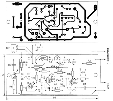
The device is made on a printed circuit board, a possible version of which is shown in Figure 2.

Figure 2. Thermostat circuit board.
The following types of parts were used for installation on the board: domestic oxide capacitors K50-35 or imported, film capacitors C1 and C9 type K73-17, the remaining small-sized ceramic capacitors. Oxide capacitors must be with a permissible temperature of at least +105 ° C, which is indicated on the case of capacitors.
Fixed resistors type MLT 0.125 or imported. Trimmer resistor R1 type СП5-28Б or another multi-turn - with its help, the upper limit of the heating will be set more accurately.
Variable resistor R17 wire type PPB-3V. Its purpose is to set the heating temperature. It is best to install this resistor in place of the old electromechanical regulator.
The temperature sensor LM335AZ, if the design of the radiator allows, should be installed in the place where the electromechanical sensor was previously installed. In this case, the old sensor, of course, will have to be removed. The connection of the sensor to the printed circuit board is best done with a twisted pair of wires. This will significantly reduce the effect of interference on the operation of the entire device as a whole.
When the regulator is designed as a separate unit, the LEDs HL1, HL2 are installed directly on the board. And if the board can be hidden inside the heater, then to install the LEDs, you will need to drill holes in the heater body. The LEDs themselves in this case should be placed on a plate of insulating material, for example, fiberglass or getinaks.
Setting up the device is easy. First of all, you should check the installation for compliance with the scheme and the absence of defects in the form of circuit paths on the board or their breakage. After that, make sure that there is a voltage of +12 V at the zener diode VD1 and a voltage of +5 V at the output of the stabilizer DA2.
After these checks, use the trimming resistor R15 to set the voltage of 3.43 V on the left output circuit of the variable resistor R17. You can verify the correct operation of the controller by rotating the variable resistor R17. In this case, you should pay attention to the LED indicators.
All measurements should be carried out relative to the negative terminal of the capacitor C4 using a digital multimeterfor example, type DT838 or the like.
Do not forget that the design does not have galvanic isolation from the electrical network. Therefore, you must be careful and careful, and it is best to use an isolation transformer. But the power of such a transformer is not enough to power the oil cooler, so for the time of commissioning (while everything is on the table and accessible), the heating element can be replaced by a conventional light bulb with a power of 25 ... 100 watts.
The temperature sensor during the adjustment process can be heated simply with a soldering iron or just mentioned lamp. In this case, the control lamp will go out when the set temperature is reached, and light up after some cooling of the sensor. The degree of cooling of the sensor depends on the hysteresis of the comparator, as described above.
Boris Aladyshkin
See also at bgv.electricianexp.com
:
