Categories: Practical Electronics, Sources of light, All about LEDs, How does it work
Number of views: 440310
Comments on the article: 52

How are LED lamps
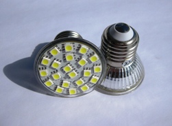
 

How are LED lampsThe article talks about the design of LED lamps. Several schemes of different complexity are considered and recommendations are given for the independent manufacture of LED light sources connected to a 220 V network.


Benefits of Energy Saving Lamps

The advantages of energy-saving lamps are widely known. First of all, it is actually low energy consumption, and in addition high reliability. Currently, the most widespread fluorescent lamps. Such a lamp power consumption 20 watts, gives the same illumination as a hundred-watt incandescent lamp. It is easy to calculate that energy savings are five times.

Recently, LED lamps are being mastered in production. The indicators of efficiency and durability are much higher than that of fluorescent lamps. In this case, electricity is consumed ten times less than incandescent lamps. The durability of LED lamps can reach 50 or more thousand hours.

New generation light sources, of course, are more expensive than simple incandescent lamps, but consume significantly less power and have increased durability. The last two indicators are designed to compensate for the high cost of new types of lamps.


Practical circuits of LED lamps

As a first example, we can consider the device of an LED lamp developed by the company "SEA Electronics" using specialized microcircuits. The electrical circuit of such a lamp is shown in Figure 1.

The scheme of the LED lamp company

Figure 1. Scheme of the LED lamp of the company "SEA Electronics"

Ten years ago, LEDs could only be used as indicators: the light intensity was no more than 1.5 ... 2 microchandels. Super bright LEDs have now appeared, in which the radiation power reaches several tens of candelas.

When using high-power LEDs in conjunction with semiconductor converters, it became possible to create light sources that can withstand competition with incandescent lamps. A similar converter is shown in Figure 1. The circuit is quite simple and contains a small number of parts. This is achieved through the use of specialized microcircuits.

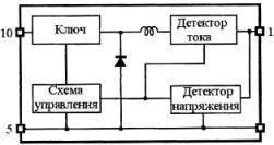
The first IC1 BP5041 chip is an AC / DC converter. Its structural diagram is shown in Figure 2.

Block diagram BP5041

Figure 2. Block diagram of BP5041.

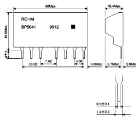
The microcircuit is made in the SIP type case shown in Figure 3.

LED lamp

Figure 3

A converter connected to a 220V lighting network provides a 5V output voltage at a current of about 100 milliamps. Connection to the network is through a rectifier made on the diode D1 (in principle, it is possible to use a bridge circuit of the rectifier) ​​and a capacitor C3. Resistor R1 and capacitor C2 eliminate impulse noise. See also - How to connect a LED lamp to a 220 V network.

The entire device is protected by an F1 fuse, the rating of which must not exceed that indicated on the diagram. Capacitor C3 is designed to smooth the ripple of the output voltage of the converter. It should be noted that the output voltage does not have galvanic isolation from the network, which is completely unnecessary in this circuit, but requires special care and observance of safety rules during manufacture and commissioning.

Capacitors C3 and C2 must be at least 450 V operating voltage. Capacitor C2 must be film or ceramic. Resistor R1 can have a resistance in the range of 10 ... 20 Ohms, which is enough for normal operation of the converter.

The use of this converter eliminates the need for a step-down transformer, which significantly reduces the overall dimensions of the device.

A distinctive feature of the BP5041 chip is the presence of a built-in inductor as shown in Figure 2, which reduces the number of attachments and the overall size of the circuit board.

As a diode D1, any diode with a reverse voltage of at least 800 V and a rectified current of at least 500 mA is suitable. The widespread import diode 1N4007 fully satisfies such conditions. a varistor VAR1 of type FNR-10K391 is installed at the input of the rectifier. Its purpose is to protect the entire device from impulse noise and static electricity.

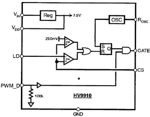
The second IC chip, type HV9910, is a PWM current stabilizer for super-bright LEDs. Using an external MOSFET transistor, the current can be set in the range from a few milliamps to 1A. This current is set by the resistor R3 in the feedback circuit. The chip is available in SO-8 (LG) and SO-16 (NG). Its appearance is shown in Figure 4, and in Figure 5 a block diagram.

Chip HV9910

Figure 4. Chip HV9910.

Block diagram of the HV9910 chip

Figure 5. Block diagram of the HV9910 chip.

Using resistor R2, the frequency of the internal oscillator can be varied in the range of 20 ... 120 KHz. With the resistance of the resistor R2 indicated in the diagram, it will be about 50 KHz.

The inductor L1 is designed to store energy while the transistor VT1 is open. When the transistor closes, the energy stored in the inductor is transmitted through the high-speed Schottky diode D2 to the LEDs D3 ... D6.

Here is the time to recall the self-induction and Lenz rule. According to this rule, the induction current always has such a direction that its magnetic flux compensates for changes in the external magnetic flux, which (change) caused this current. Therefore, the direction of the EMF of self-induction has a direction opposite to the direction of the EMF of the power source. That is why the LEDs are turned on in the opposite direction with respect to the supply voltage (pin 1 of IC2, indicated on the diagram as VIN). Thus, the LEDs emit light due to the EMF of the self-induction coil L1.

In this design, 4 superbright LEDs of the TWW9600 type are used, although it is quite possible to use other types of LEDs manufactured by other companies.

To control the brightness of the LEDs in the chip has an input PWM_D, PWM - modulation from an external generator. In this scheme, such a function is not used.


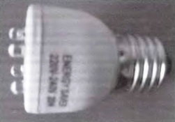
If you are making such an LED lamp yourself, you should use a housing with a screw base of size E27 from an unusable energy-saving lamp with a power of at least 20 watts. The appearance of the structure is shown in Figure 6.
Homemade LED lamp

Figure 6. Homemade LED lamp.

Although the described scheme is quite simple, it is not always possible to recommend it for self-production: either you will not be able to buy the parts indicated on the scheme, or insufficient qualification of the assembler. Some may just be scared: “What if I won’t succeed?”. For such situations, you can offer several more simpler options both in circuitry and in the acquisition of parts.


Simple LED home lamp

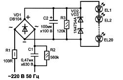
A simpler diagram of the LED lamp is shown in Figure 7.

Simple LED home lamp

Figure 7

This diagram shows that a bridge rectifier with capacitive ballast is used to power the LEDs, which limits the output current. Such power supplies are economical and simple, not afraid of short circuits, their output current is limited by the capacitance of the capacitor. Such rectifiers are often called current stabilizers.

The role of capacitive ballast in the circuit is performed by capacitor C1. With a capacitance of 0.47 μF, the operating voltage of the capacitor must be at least 630 V. Its capacity is designed so that the current through the LEDs is about 20 mA, which is the optimal value for LEDs.

The ripple of the bridge rectified voltage is smoothed by the electrolytic capacitor C2. To limit the charging current at the time of switching on, a resistor R1 is used, which also serves as a fuse in emergency situations.Resistors R2 and R3 are designed to discharge capacitors C1 and C2 after disconnecting the device from the network.

To reduce the dimensions, the operating voltage of the capacitor C2 was selected to be only 100 V. In case of breakdown (burnout) of at least one of the LEDs, the capacitor C2 will be charged to a voltage of 310 V, which will inevitably lead to its explosion. To protect against this situation, this capacitor is shunted by the zener diodes VD2, VD3. Their stabilization voltage can be determined as follows.

At a rated current through the LED of 20 mA, a voltage drop is created on it, depending on the type, within 3.2 ... 3.8 V. (A similar property in some cases allows the use of LEDs as zener diodes). Therefore, it is easy to calculate that if 20 LEDs are used in the circuit, then the voltage drop across them will be 65 ... 75 V. It is at this level that the voltage across the capacitor C2 will be limited.

Zener diodes should be selected so that the total stabilization voltage is slightly higher than the voltage drop across the LEDs. In this case, during normal operation, the zener diodes will be closed and will not affect the operation of the circuit. The 1N4754A zener diodes indicated on the circuit have a stabilization voltage of 39 V, and connected in series - 78 V.

If at least one of the LEDs breaks, the zener diodes will open and the voltage on the capacitor C2 will be stabilized at 78 V, which is clearly lower than the operating voltage of the capacitor C2, so there will be no explosion.

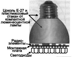
The design of a home-made LED lamp is shown in Figure 8. As can be seen from the figure, it is assembled in a housing from an unusable energy-saving lamp with an E-27 base.
Simple LED home lamp

Figure 8

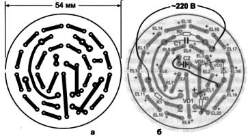
The printed circuit board on which all the parts are placed is made of foil fiberglass in any of the ways available at home. To install the LEDs, 0.8 mm diameter holes were drilled on the board, and 1.0 mm for the remaining parts. A circuit board drawing is shown in Figure 9.

Printed circuit board and the location of parts on it

Figure 9. The printed circuit board and the arrangement of parts on it.

The location of parts on the board is shown in Figure 9c. All parts except LEDs are installed on the side of the board, where there are no printed tracks. A jumper is also installed on the same side, also shown in the figure.

After installing all the parts on the side of the foil, LEDs are installed. Installation of LEDs should begin from the middle of the board, gradually moving to the periphery. The LEDs must be sealed in series, that is, the positive terminal of one LED is connected to the negative terminal of the other.

The diameter of the LED can be any within 3 ... 10 mm. In this case, the conclusions of the LEDs should be left at least 5 mm long from the board. Otherwise, the LEDs can simply be overheated when soldering. The duration of soldering, as recommended in all manuals, should not exceed 3 seconds.

After the board is assembled and adjusted, its conclusions must be soldered to the base, and the board itself is inserted into the case. In addition to the indicated case, it is possible to use a more miniature case, however, it will be necessary to reduce the size of the printed circuit board, not forgetting, however, the dimensions of the capacitors C1 and C2.

See also: LED lamp repair history


The simplest LED lamp design

Such a circuit is shown in Figure 10.
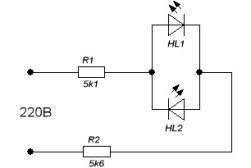
The simplest LED lamp design

Figure 10. The simplest LED lamp design.

The circuit contains a minimum number of parts: only 2 LEDs and quenching resistor. The diagram shows that the LEDs are turned on in parallel - in parallel. With this inclusion, each of them protects the other from the reverse voltage, which is small for the LEDs, and the mains voltage clearly can not stand it. In addition, such a double inclusion will increase the flicker frequency of the LED lamp to 100 Hz, which will not be noticeable to the eye and will not bore the eyesight. It is enough to recall here how, in order to save money, ordinary incandescent lamps were connected through a diode, for example, in entrances. They acted very unpleasantly on vision.

If two LEDs are not available, then one of them can be replaced with a conventional rectifier diode, which will protect the emitting diode from the reverse voltage of the network. The direction of its inclusion should be the same as that of the missing LED. With this inclusion, the flicker frequency of the LED will be 25 Hz, which will be noticeable to the eye, as already described just above.

To limit the current through the LEDs at the level of 20 mA, the resistor R1 must have a resistance in the range of 10 ... 11 KOhm. At the same time, its power should be at least 5 watts. To reduce heating, it can be composed of several, best of all three, 2 W resistors.

LEDs can be used the same as those mentioned in previous schemes or which can be purchased. When buying, you should accurately know the brand of the LED in order to determine its rated direct current. Based on the magnitude of this current, the resistance of the resistor R1 is selected.

The design of the lamp assembled according to this scheme differs little from the two previous ones: it can also be made in the housing from an unusable energy-saving fluorescent lamp. The simplicity of the circuit does not even imply the presence of a printed circuit board: the parts can be connected by wall mounting, therefore, as they say in such cases, the design is arbitrary.

See also at i.electricianexp.com:

  • Some simple LED power schemes
  • Homemade LED Strip Light
  • LED Lamp Repair - Replacing a LED in a failed lamp
  • Simple emergency light source
  • How to make an LED from a compact fluorescent lamp

  •  
     
    Comments:

    # 1 wrote: | [quote]


    As for the economy and economy - bullshit.
    The technical side is for dummies.
    The value of the article is with a minus sign.

     
    Comments:

    # 2 wrote: andy78 | [quote]


    Comments:

    # 3 wrote: | [quote]


    Very helpful for me. 20 years with one hand. I don’t even think about electro-work. And your site helps in the house at home, neighbors, relatives.

     
    Comments:

    # 4 wrote: | [quote]


    Ignore the grunts. Over time, after the establishment of production, the cost of LED lamps will come down. And the article is quite informative. I tell you, as an electrician, "honored" to the head of the enterprise’s energy.

     
    Comments:

    # 5 wrote: | [quote]


    The information for acquaintance is useful, but slammed from the source!

     
    Comments:

    # 6 wrote: andy78 | [quote]


    Andrey, This article is not reprinted from other sites, but written by Boris Aladyshkin specifically for the i.electricianexp.com project. True, the article used the schemes and specifications of manufacturers of LED lamps.

     
    Comments:

    # 7 wrote: | [quote]


    Thanks to the author for the scheme. Well, (Fedor) were and will be - do not pay attention. To power LEDs from 220 I use old charges from mobile phones plus a zener diode at the output. Three table lamps have been working for more than six months - consumed by P no more than 6 - 7 watts

     
    Comments:

    # 8 wrote: | [quote]


    Good article, I'll try to figure something out. Thanks!

     
    Comments:

    # 9 wrote: | [quote]


    why fence a garden if you can take an old charger from a mobile phone and a zener diode. Chargers are for different currents, so put the required number of LEDs

     
    Comments:

    # 10 wrote: | [quote]


    From experience with Chinese "corn", I can say that the original ballast capacitor is very hot and often shoots, although the voltage on it is much lower than the working one. Installing K73-11 solved the problem. The resistor tried to set, as in the circuit, but it melts the neighboring wires and the case itself. Dimensions do not allow it to be placed at the proper distance. Less common are samples with defective LEDs that die quickly. Also, sometimes heating of the electrolytic capacitor was observed. Why didn’t understand. On tests with them, everything is ok.

    When you rotate something, the strobe effect is clearly visible, so there is still an ordinary lamp in the chandelier to compensate for it. It is also needed to work with a dimmer. Without it, the adjustment does not work.Either the power is unaccountably small, or the capacitive load is too dominant.

     
    Comments:

    # 11 wrote: andr | [quote]


    “Concerning the economy and economy” - wait and see, it’s not so long to wait (at the current rate of scientific and technical progress).

    "The technical side is for dummies."

    On behalf of the dummies:

    Thanks to the author, a good general orientation.

    And information for thought at your leisure.

    "The value of the article is with a sign": plus + plus.

     
    Comments:

    # 12 wrote: | [quote]


    As for the amount of light, it has long been estimated that LEDs are slightly inferior to fluorescent lamps, but due to the directivity of the radiation, they still win. Again, due to the directivity, it is difficult to obtain uniform diffused light.

    As for the rest, the article is good, it’s only interesting how accessible are the microcircuits from the example, often the “specialized” microcircuits are specialized because they are custom-made and do not go on sale.

    An interesting comment by Artem about the strobe effect, the LEDs really do not have inertia, he himself made a car strobe, they are used as a flash in phones. Conclusion, it is impossible to use with ballast from the network.

     
    Comments:

    # 13 wrote: | [quote]


    I read the article in detail with interest. I think that it will be useful for young specialists, taking into account some well-founded comments contained in these comments

     
    Comments:

    # 14 wrote: | [quote]


    Article useful for general development. The man made a short review. But there are inaccuracies. The flicker frequency of the LED with a resistive ballast will be equal to the network frequency, i.e. 50 Hz. Oncoming LEDs due to the glow in different half-periods of the network will give a flicker of 100 Hz, as rightly indicated a little earlier.

     
    Comments:

    # 15 wrote: Yuri | [quote]


    You should try to make a good article yourself and change the lamps at home to LEDs, otherwise the payment for light already can afford it, and what will happen next ...

     
    Comments:

    # 16 wrote: Kondrat | [quote]


    Something very powerful now took up the LED lamps. This is very alarming!

     
    Comments:

    # 17 wrote: | [quote]


    I bought in China such a lamp "Simple LED Lamp" with 60 LEDs, after about three weeks it began to turn itself off and on. I disassembled, the LEDs do not ring, but when 3v is supplied, they light up, one pierced when 5v is applied. After that, the lamp did not work for long. In general, as a result, I short-circuited it and everything works. True lighting is bad, like an incandescent lamp of 25 watts maximum.

     
    Comments:

    # 18 wrote: | [quote]


    I often read your articles. Given the rapid development of the element base, I like the approach when using modern energy-saving technologies. Many of my acquaintances and friends were very surprised to learn about your halogen lamp power supply, a simple training course and the use of measuring instruments. I ask you to be proud that you are sometimes brainwashed, only Emele the fool he still lies on his stove and waits for the pike to be caught for him.

    It is difficult to judge on the Internet the qualifications of one or another author. The very fact of reasoning about a particular device indicates the importance of your site.

    Thank you from me and my friends for articles and practical work. After all, everything simple lies underfoot. Stewards and philosophers would be better off building space projects for nuclear plants to give light to underdeveloped areas. And it is enough to throw away (turn over to copper) the old transformer, put energy-saving lamps and use pulse sources. Instead of induction motors, install stepper motors on torsion fields on the drives. Then there will be no 10 billion nuclear power plant projects. erection, 12 mld. disposal and God forbid Chernobyl, Fukushima and other technogenic pies.

     
    Comments:

    # 19 wrote: Pasha | [quote]


    About the life of LED lamps, they usually lie a lot - they can degrade in a couple of months. And the price of an LED lamp is cosmic!

     
    Comments:

    # 20 wrote: George | [quote]


    LEDs are better than LDS for safety reasons (do not contain mercury) and turn on instantly. But like the LDS they have far from an ideal spectrum, which is why their eyes get tired and the rather big price. No matter what they say, for now, ordinary incandescent lamps are preferable if you value your eyesight and do not want to overspend ...

     
    Comments:

    # 21 wrote: Dmitriy | [quote]


    Good LEDs are now superior to LDS in efficiency (120 lm / watt versus 60-80), service life (100 thousand hours), and spectrum (continuous, because special phosphors have been developed that are not used in LDS because of cost ( smear the whole flask or chip 1 * 1mm) or instability to mercury vapor and ultraviolet. But such LEDs are expensive - 50 rubles per watt or 120 lumens. And this is just the diode itself. I don’t see the point of making an E27 lamp from them, unless I try. The lamp is more 5W will heat up to a temperature at which the diodes quickly degrade.5W = 600 lumens, somewhere between 40 and 60 watts of a conventional lamp Coy brightness.

    It makes sense to screw the diodes to the duralumin plate, a plastic / glass diffuser on the plate, control the temperature - it will work for years)

    To waste money? An incandescent bulb of 100 watts, works for 1000 hours (one and a half months of continuous operation). During this time, it consumes 100 kW / h - that is, 350 r. That is, CFL has already paid off during this time. Diodes are still expensive, which is true then true, but with proper operation it is the cheapest way of lighting.

     
    Comments:

    # 22 wrote: Paul | [quote]


    The article is still UG, the author was too lazy to read datasheets on microcircuits that he uses ...
    The schemes that are presented, purely theoretical, in principle can not work. At least due to the fact that the VR5041A5 has an output voltage of 5 V and the minimum input voltage of the HV9910 is 8 V. Plus, the GND of the HV9910 is not connected to the negative plates C1, C3, etc. ... There is still more to go on.
    NOBODY COLLECTED AND TESTED the given circuit. Otherwise, they were ashamed to post this nonsense.
    People, do not get fooled. Read datasheets on microcircuits and examples of their application, everything is correctly written and tested there.

     
    Comments:

    # 23 wrote: andy78 | [quote]


    Paul, you're not right. The article is good, written easily and interestingly. The article is called "How LED Lamps Are Designed" and is a good overview of the topic. Naturally, the schemes presented in the article are more interesting for a general understanding of the device and the principles of operation of LED lamps. For self-assembly, only the latest scheme is suitable. And so, this is just a review about LED lamps, and nothing else was implied here.

     
    Comments:

    # 24 wrote: | [quote]


    It is a pity that you did not understand the device of the LED itself ...

     
    Comments:

    # 25 wrote: Andrew | [quote]


    I read a lot about LED lamps. Everything on your site is very clearly explained. I believe that LED lamps are a very promising thing!

     
    Comments:

    # 26 wrote: Sergey Kolomiets | [quote]


    Regarding the article "How LED lamps are arranged," I want to add only one thing. Your site is actively read not only in Russia. In Bulgaria, 1 kWh costs 12 euro cents (about 1 p.), The price of superbright LEDs is the same. If in bulk - 10-15% cheaper. Maths! - Count for yourself ... Therefore, we have LED lamps, an extremely profitable thing. Thanks for the nice article!

    With best regards, dipl.eng.Sergey Kolomiets

     
    Comments:

    # 27 wrote: | [quote]


    The article is really good one pluses.
    I practically use old chargers from phones to power the LEDs, I do not connect zener diodes.

    Explain what the zener diodes will give?

     
    Comments:

    # 28 wrote: Joystick | [quote]


    Chinese fakes do not live long.

     
    Comments:

    # 29 wrote: | [quote]


    Comments:

    # 30 wrote: Andrew | [quote]


    SergeiZener diodes are used to stabilize the voltage. The voltage drop across them is practically independent of the flowing current.

     
    Comments:

    # 31 wrote: | [quote]


    "The flicker frequency of the LED with a resistive ballast will be equal to the mains frequency, ie 50 Hz. The counter-activated LEDs due to the glow in different half-periods of the network will give a flicker of 100 Hz, as rightly indicated a little earlier."

    Here is the real bullshit !! If not in the subject, better chew orbits :)))))

     
    Comments:

    # 32 wrote: | [quote]


    Sorry - did not understand what the argument is about ??? This article, like others on the site, is just a class !!! Everything is written simply and accessible !!! THANKS!!!

     
    Comments:

    # 33 wrote: | [quote]


    Who can tell me why when I turn off the LED bulbs with a switch, they still glow a little? It doesn’t turn off completely. Because of this, instead of one LED lamp, it is necessary to add one incandescent lamp to the lamp, then all the lamps go out. I suspect that the problem is in the resistance of these lamps ... How to fix the problem so as not to use an incandescent lamp for a complete network burst?

     
    Comments:

    # 34 wrote: MaksimovM | [quote]


    Sergei, the cause of the glow of LED lamps when off can be the presence of backlight in the light switch. If there is one, then so that the bulbs do not glow when the switch is off, the backlight must be turned off. Well, in general, what about the resistance of the lamps, if the current should not flow through the lamps when the switch is off, since the circuit is broken? Perhaps the matter is the resistance of the switch? When the switch is off, the resistance between the contacts should be large. If for one reason or another the resistance is low, then maybe there is a small potential on the lamp, which is the cause of the glow of the lamps. Therefore, check the switch, in particular the contacts, for a gap between them when the switch is off. Very often, circuit breakers fail and can poorly close or open contacts. It is also possible that there is interference in the cable that feeds this lamp from another wiring line that runs nearby. Check the voltage on the lamp holder when the switch is off.

     
    Comments:

    # 35 wrote: Alexei | [quote]


    LEDs, like all semiconductors, are sensitive to all kinds of electromagnetic interference, and this may be one of the reasons for their partial illumination when the switch is off ...

     
    Comments:

    # 36 wrote: | [quote]


    For some reason, everyone has forgotten that the LEDs for such lamps emit ultraviolet light, which results in a white glow of the phosphor that is contained in the same LEDs. Something similar to an ordinary "daylight" lamp only without a glass shell that partially does not allow ultraviolet to pass out. Take care of the eyes of gentlemen, eye operations in domestic clinics are very expensive.

    Quote: GroOld
    Oncoming LEDs due to the glow in different half-periods of the network will give a flicker of 100 Hz

    Is it interesting like 100 hertz? One half-cycle is 25 hertz. Two to twenty-five stolnik will not equal how, but all the same 50 hertz.

     
    Comments:

    # 37 wrote: Igor | [quote]


    Half of the details can be ejected from the circuit in Fig. 7, while improving efficiency.
    The efficiency of the circuit in Figure 10 ka for a steam locomotive is obviously much less than for an incandescent bulb.

     
    Comments:

    # 38 wrote: | [quote]


    Good time!

    Question to the experts:

    Given: a lamp with 7 halogen lamps with a power of 20 W each, voltage - constant, 12 V, transformer for 140 W.

    I decided to replace the halogen lamps with LED ones.

    As a result, I bought 7 Osram LED lamps with a power of 6 W each for a direct current of 12 V.

    Question:

    Periodically, part of the lamps does not turn on (problems with contacts in the lamp are excluded - halogen lamps work without problems when replacing). Turning off the extinct lamps is carried out by the method of "physical" exposure - by pressing the edges of the lamp.

    What could be the problem? The transformer provides halogen operation without any problems.

    Thanks in advance.

     
    Comments:

    # 39 wrote: Roll | [quote]


    Gray,
    The half-period is NOT 25 Hz, but the same 50 Hz (but with "pauses"). “The LEDs that are turned on due to the glow in different half-periods of the network will give a flicker of 100 Hz,” because one LED (positive half-wave) will flash 50 times per second and turned on again 50 times. As a result, 100 flashes per second, i.e. 100 Hz ..

     
    Comments:

    # 40 wrote: | [quote]


    I think the distribution of LED lamps in the future should go this way: since the lighting network is now made separately from outlets, it’s more profitable to install on the dashboard one stabilized DC source of 10-12 volts for the entire lighting network, and make all the lamps low voltage with direct connection to the lighting network. This will significantly reduce the cost of LED lamps. It would not hurt to transfer all household appliances to food under reduced voltage. As a result, there would be no need to make complex power supplies on all audio, video household appliances. Leave only 220 volts to power consumers of high power el. kettles, washing machines, vacuum cleaners, etc. with excellent shape plugs and sockets.

     
    Comments:

    # 41 wrote: | [quote]


    What disputes do our LED lamps cost from 150-200 r. There are 600-800 p. But for idiots. I have 7 watt bulbs for a year (era a55-7w-827-e27 600lm). And they do not respond to switches with LEDs and neon.

     
    Comments:

    # 42 wrote: | [quote]


    Konstantin, the fact is that an electronic transformer often comes to halogen lamps! AC! current. This is not a power supply. It turns on for 1 half-cycle and if there is no load (minimum allowable power), it does not work further.

    In addition, when you touch, "breakdown due to the formation of a capacitance with the earth" occurs

    The answer is the main option: you need a switching power supply and a constant voltage.

    Option 2: often met LED lamps in which the tip of the central channel is slightly shorter than the standard.

    Option 3: can you have 220 LED bulbs?

    Central contact ...

     
    Comments:

    # 43 wrote: | [quote]


    Sergei,
    MaksimovM,
    You did not take into account the capacity of the cable going to the switch. This capacity was enough for the flickering of energy-saving lamps, and for LEDs with a driver there is enough for flickering, and for those assembled in a simple scheme without a driver, it is enough for constant illumination.

     
    Comments:

    # 44 wrote: | [quote]


    They asked to repair 2 lamps assembled according to such a scheme. We bought them in China (alibaba or aliexpress) via the Internet. The quality is lousy, the power is 7 W, it costs 14 SMD LEDs of 0.5 W each, they are installed on a getinax board without a heat sink, so one LED flew in both. There is no zener diode, so the electrolyte thumped. I repaired it, but I don’t know how long it will work. It is easy to open the case, so anyone who buys this can be checked how the lamp is assembled, the quality will be on a thin film glued to an aluminum plate.

     
    Comments:

    # 45 wrote: | [quote]


    Answering Sergey’s question: why when I turn off the LED bulbs with a switch, do they still glow a little? I want to share my experience. In my practice, I met different things with the described. But most often this is the connection of the ZERO (N) wire instead of the PHASE (L) through the SWITCH. Check the indicator if there is a phase in the cartridge (where the bulb is screwed in) with the switch off. If there is (the indicator is lit), then in the junction box, swap the wire from the cartridge with the wire from the switch. Correctly, it should be like this: One wire from the cartridge (where the bulb is screwed from the extreme contact), in the junction box, connects to the ZERO (N) input wire. The second wire from the same cartridge (middle contact) in the junction box must be connected to one wire of the switch. And the second wire from the switch must be connected, in the junction box, to the PHASE (L) input wire.

     
    Comments:

    # 46 wrote: Alexandr | [quote]


    Unfortunately, the resistor power is not indicated in the diagram in Figure 10.What if someone decides to collect?
    But 220/10200 = 21 mA. So the power on the resistor is 4.6 watts. A resistor of this power has a considerable size, moreover, it will warm up ... and you need to take at least 10 watts.

     
    Comments:

    # 47 wrote: | [quote]


    Tell me how you can eliminate the flashing of the LED lamp from the work of an electric drill, a refrigerator.

     
    Comments:

    # 48 wrote: Andrew | [quote]


    LED lamps dominate the industrial and home lighting market.

    LEDs were first shown in the early 1960s, but were low power and could only emit light in the low, red spectrum. For many years, they have been used mainly as indicators. The latest history of LEDs began in 1990 with the manufacture of the first blue by the Japanese company Nichia Chemical Industries (the invention for which the researchers received the Nobel Prize in October 2014), and then the white LEDs.

    The economic prospects of LED lighting were described by the authors of the American program in 2000 as follows: “If incandescent bulbs are replaced by LEDs by 2020, the resulting energy savings will be equivalent to the option to abandon the construction of 100 nuclear power plants and reduce emissions of hydrocarbon combustion products by hundreds of millions tons per year. "

    In the early years of the 21st century, investments in the research and development of LEDs in Japan, the USA, Korea, and China amounted to hundreds of millions of dollars. After 5-6 years, these investments began to pay off.

    Since 2005, the LED market has grown by 11% per year, from $ 4 billion to $ 5.5 billion in 2008. Then, despite the economic crisis, it continued to grow by 4% per year. Since 2010, the LED market has been growing at 15% per year and it is predicted that such growth will continue.

    The luminous efficiency of LED lighting devices by 2020 will reach 243 lm / W. Digitimes Research suggests that prices for LED products will drop annually by 20-30%.

    The consumption of LEDs is also increasing in residential lighting systems. CEO Philips Taiwan Ltd. Edward Poe predicts that by 2020, LEDs will occupy 75% of the lighting market and 100% of the digital advertising market (since even LCD screens now use LED backlighting).

     
    Comments:

    # 49 wrote: | [quote]


    LED lamps can work even more efficiently and economically. You can make the LED lamp work 3 times more economically, judging by the wattmeter.

     
    Comments:

    # 50 wrote: Vlad | [quote]


    When these lamps burn out after half a year - what is their efficiency ???

    You just immediately give a large amount to the seller of the lamp, and then try to save on the cost of electricity spent.

     
    Comments:

    # 51 wrote: Anatoly | [quote]


    The last circuit with a resistor very clearly shows the essence of saving LED lamps (let us leave alone the possibility of its technical implementation) most importantly, the circuit parameters are chosen correctly. Now let's calculate. With a resistor resistance of 10 kOhm and a voltage of 220 volts, the current in the circuit is 0.022 amperes or 22 milliamps. Power converted to heat on a resistor is 4.84 watts. But the LED also has some internal resistance. Let it be a white LED based on a blue LED with a phosphor lens and a voltage drop of 3 volts on it, with a power of 0.1 watts. Then the resistance of the LED will be about 90 ohms and the current will be 0.0218 amperes or 21.8 milliamps. As we see, the internal support of the LED on the current in the circuit affects very little. At the same time, the current flowing through the LED is important for the glow, and at the internal resistance of the LED, the current converts the received power into heat and will heat the LED. Even if this power is considered conditionally useful, then compared to the power converted to heat on the resistor, KPD schemes - 0.1 / 4.84 = 0.021 or 2.1%, for an incandescent lamp and then K.P.D. more. And so all LED lamps are arranged.That is, the power indicated on the package of lamps is nothing more than the power of heat losses in the lamp. Of course, we get as much light from an LED lamp as from an incandescent lamp, but at the same time we waste a lot less energy on heating the lamp, but it’s not saving energy, saving electricity is reducing its usable cost per unit of production, and this is reducing losses electricity for lighting. Given that this also requires reactive power in LED lamps and they create higher harmonics in the alternating current network, the reduction in energy losses is very relative.

     
    Comments:

    # 52 wrote: Yuri | [quote]


    The author is well done, the article is good. Even just sit with a soldering iron to solder. And to buy ready-made is easy, if it is so urgently needed. And if you talk like that "Fedya", you have not wondered why there are still short-wave radio hams when there is Internet?