Categories: Practical Electronics, Electrician Secrets
Number of views: 186978
Comments on the article: 5
How to get twenty-four volts from a computer power supply
 The article explains how to remake a conventional computer power supply for a voltage of 24 volts.
In some cases, there is a need for powerful power supplies for various equipment, designed for a voltage of 24 volts.
In this article I will tell you how you can remake a conventional computer power supply both ATX and AT for a voltage of 24 V. Also, from several such blocks, you can compose any voltage to power all kinds of devices.
For example, to power a local PBX UATSK 50 / 200M, designed for a voltage of 60 V and a power of about 600 watts, the author of the article replaced the usual huge transformer units with three small computer power supplies that neatly fit on the wall next to the power switch and almost did not create any noise.
Alteration is the addition of two power diodes, an inductor and a capacitor. The circuit is similar to the + 12V power bus after a pulse transformer, only the diodes and the polarity of the capacitor are reversed, as shown in the figure (filter capacitors are not shown).
The beauty of this alteration is that the protection and voltage stabilization circuits remain intact and continue to work in the previous mode. It is possible to get a voltage other than 24 volts (for example, 20 or 30), but for this you will have to change the parameters of the reference voltage divider of the control chip and change or disable the protection circuit, which is already more difficult to do.
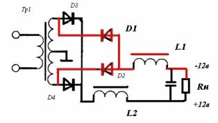
Additional diodes D1 and D2 are mounted through insulation on the same radiator as the rest, in any convenient place but with a full spot of contact with the radiator.
The L1 throttle is mounted in any place available on the board (it can be glued), but it should be noted that in different models and brands of power supplies it will heat up differently, possibly even more than already standing on the circuit + L2 (depends on the quality of the power supply) . In this case, you must either select the inductance (which should not be less than the standard L2) or mount it directly on the housing (through insulation) to remove heat.
 You can check the unit at full load or at the load for which it will work for you. In this case, the housing must be completely closed (as expected). When checking, it should be observed whether the radiators, on which the semiconductors and the additionally installed choke are connected via the -12v circuit, are not overheating. For example, a power supply rated at 300 watts can be loaded with a current of 10-13A at a voltage of 24V. It will not be superfluous to check the output voltage ripple with an oscilloscope.
It is also very important to note that if two or more units connected in series work together, then the case (mass) of the circuit must be DISCONNECTED from the metal case of the power supply unit (I did this by simply cutting the tracks in the places where the board is attached to the chassis). Otherwise, you will get a short circuit either through the ground wire of the power cords or by touching the housings to each other. For clarity, the proper operation of the unit, you can bring out a light bulb or LED.
The difference between the alteration of the AT and ATX standards is only in the launch of the unit. The AT starts working immediately after turning on the 220 V network, and the ATX must either be triggered by the PS-ON signal, as is done on a computer, or ground the wire of this signal (usually it goes to the control leg of the chip). In this case, the unit will also start when it is connected to the network.
See also at bgv.electricianexp.com
: