Categories: Featured Articles » Practical Electronics
Number of views: 160636
Comments on the article: 6
The use of the chip KR1182PM1. Soft start of the electric motor
Motor soft starters
 Soft start of the electric motor has recently been applied more and more often. The fields of its application are diverse and numerous. This is industry, electric transport, utilities and agriculture. The use of such devices can significantly reduce the starting load on the electric motor and actuators, thereby extending their service life.
Inrush currents
Starting currents reach values 7 ... 10 times higher than in the operating mode. This leads to "subsidence" of voltage in the supply network, which negatively affects not only the work of other consumers, but also the engine itself. The start-up time is delayed, which can lead to overheating of the windings and the gradual destruction of their insulation. This contributes to premature failure of the motor.
Soft starters can significantly reduce the starting load on the electric motor and mains, which is especially important in rural areas or when the engine is powered by an autonomous power station.
Actuator overloads
At the time of starting the engine, the moment on its shaft is very unstable and exceeds the nominal value by more than five times. Therefore, the starting loads of the actuators are also increased in comparison with the work in the steady state and can reach up to 500 percent. The instability of the torque during start-up leads to shock loads on the gear teeth, cutting dowels, and sometimes even twisting of the shafts.
The soft starters of the electric motor significantly reduce the starting loads on the mechanism: gaps between the gear teeth are smoothly selected, which prevents their breakdown. In belt drives drive belts are also smoothly pulled, which reduces wear on the mechanisms.
In addition to a soft start, the operation of mechanisms has a beneficial effect on the smooth braking mode. If the engine drives the pump, then smooth braking avoids water hammer when the unit is turned off.
Industrial soft starters
Soft starters currently produced by many companies, for example Siemens, Danfoss, Schneider Electric. Such devices have many user-programmable features. These are acceleration time, braking time, overload protection and many other additional functions.
With all the advantages, branded devices have one drawback - a fairly high price. However, you can create a similar device yourself. Its cost will turn out to be small.
Soft starter on the KR1182PM1 chip
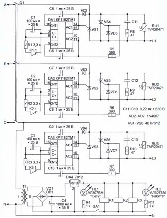
IN the first part of the article talked about specialized chip KR1182PM1representing a phase power regulator. Typical schemes for its inclusion, devices for the smooth start of incandescent lamps and simply power regulators in the load were considered. Based on this microcircuit, it is possible to create a fairly simple three-phase motor soft starter. The device diagram is shown in Figure 1.
Figure 1. Scheme of the soft starter.
A soft start is carried out by gradually increasing the voltage on the motor windings from zero to nominal. This is achieved by increasing the opening angle of the thyristor keys in a time called the start time.
Circuit description
The design uses a three-phase electric motor of 50 Hz, 380 V. The motor windings connected by a "star" are connected to the output circuits indicated on the diagram as L1, L2, L3. The midpoint of the "star" is connected to the network neutral (N).
The output keys are made on thyristors connected counterclockwise. The design used imported thyristors type 40TPS12. At a low cost, they have a sufficiently large current - up to 35 A, and their reverse voltage is 1200 V. In addition to them, there are several more elements in the keys. Their purpose is as follows: RC damping circuits connected in parallel to the thyristors prevent false switching of the latter (R8C11, R9C12, R10C13 on the circuit), and switching interference with an amplitude exceeding 500 V is absorbed using the varistors RU1 ... RU3.
As control nodes for the output keys are used chips DA1 ... DA3 type KR1182PM1. These microcircuits were considered in sufficient detail in the first part of the article. Capacitors C5 ... C10 inside the microcircuit form a sawtooth voltage, which is synchronized by the network. The thyristor control signals in the microcircuit are formed by comparing the sawtooth voltage with the voltage between the terminals of the microcircuit 3 and 6.
To power the relay K1 ... K3, the device has a power supply, which consists of only a few elements. This is a transformer T1, a rectifier bridge VD1, a smoothing capacitor C4. At the output of the rectifier, an integral stabilizer DA4 of type 7812 is installed, which provides a voltage of 12 V at the output, and protection against short circuits and overloads at the output.
Description of the operation of the soft starter motors
Mains voltage is applied to the circuit when the circuit breaker Q1 closes. However, the engine has not yet started. This is because the relay windings K1 ... K3 are still de-energized, and their normally-closed contacts bypass the pins 3 and 6 of the DA1 ... DA3 circuits through the resistors R1 ... R3. This circumstance does not allow capacitors C1 ... C3 to be charged, therefore, the control pulses of the microcircuit do not produce.
Start up the device
When the toggle switch SA1 is closed, the voltage of 12 V turns on the relay K1 ... K3. Their normally-closed contacts open, which makes it possible to charge capacitors C1 ... C3 from internal current generators. Together with an increase in voltage across these capacitors, the opening angle of the thyristors also increases. This achieves a smooth increase in voltage across the motor windings. When the capacitors are fully charged, the turn-on angle of the thyristors will reach the maximum value, and the frequency of rotation of the electric motor will reach the nominal.
Engine shutdown, smooth braking
To turn off the engine, open the SA1 switch. This will trip the relay K1 ... K3. Their normally closed contacts will close, which will lead to the discharge of capacitors C1 ... C3 through resistors R1 ... R3. The discharge of capacitors will last a few seconds, during which time the engine will stop.
When the engine is started, significant currents can flow in the neutral wire. This is because during smooth acceleration the currents in the motor windings are not sinusoidal, but you should not be particularly afraid of this: the start-up process is quite short-lived. In the steady state, this current will be much less (no more than ten percent of the phase current in the nominal mode), which is due only to the technological spread of the winding parameters and the phase imbalance. It is already impossible to get rid of these phenomena.
Parts and construction
The following parts are required to assemble the device:
A transformer with a power of not more than 15 W, with a voltage of the output winding 15 ... 17 V.
Any relay with a voltage of 12 V coil having a normally-closed or switching contact, for example TRU-12VDC-SB-SL, can be used as a relay K1 ... K3.
Capacitors C11 ... C13 of type K73-17 for an operating voltage of at least 600 V.
The device is made on a printed circuit board. The assembled device should be placed in a plastic case of suitable sizes, on the front panel of which there is a switch SA1 and LEDs HL1 and HL2.
Motor connection
The connection of the switch Q1 and the motor is carried out by wires, the cross section of which corresponds to the power of the latter.The neutral wire is the same wire as the phase wire. With the ratings of the parts indicated on the diagram, it is possible to connect engines with power up to four kilowatts.
If you intend to use an engine with a power of not more than one and a half kilowatts, and the start frequency will not exceed 10 ... 15 per hour, then the power dissipated on the thyristor keys is insignificant, therefore, radiators can be omitted.
If it is supposed to use a more powerful engine or starts will be more frequent, installation of thyristors on radiators made of an aluminum strip will be required. If the radiator is supposed to be used common, then the thyristors should be isolated from it using mica gaskets. To improve the cooling conditions, you can use the heat transfer paste KPT - 8.
Check and set up the device
Before switching on, first of all, check the installation for compliance with the circuit diagram. This is a basic rule, and it is impossible to deviate from it. After all, neglecting this test can lead to a heap of charred parts, and for a long time discourage doing “experiments with electricity”. The errors found should be eliminated, because nevertheless this circuit is powered by the network, and the jokes are bad with it. And even after this test, it is too early to connect the engine.
First, instead of the engine, connect three identical incandescent lamps with a power of 60 ... 100 watts. During testing, it should be ensured that the lamps “light up” evenly.
The non-uniformity of the on-time is due to the variation in capacitances of capacitors C1 ... C3, which have a significant tolerance in capacity. Therefore, it is better to immediately select them using the device before installation, at least with an accuracy of up to ten percent.
The turn-off time is also due to the resistance of the resistors R1 ... R3. With their help, you can align the time off. These settings should be made if the spread in the on / off time in different phases exceeds 30 percent.
The engine can only be connected after the above checks have passed normally, not to say even perfectly.
What else can be added to the design
It has already been said above that such devices are currently produced by different companies. Of course, it is impossible to repeat all the functions of branded devices in such a makeshift, but one still, it will probably be possible to copy.
It's about the so-called bypass contactor. Its purpose is as follows: after the engine has reached rated speed, the contactor simply bridges the thyristor keys with its contacts. Current flows through them, bypassing the thyristors. This design is often called bypass (from English bypass - bypass). For such an improvement, additional elements will have to be added to the control unit.
Boris Aladyshkin
See also at bgv.electricianexp.com
:

