Categories: Featured Articles » Practical Electronics
Number of views: 55754
Comments on the article: 0
Logic chips. Part 4
 After meeting in previous parts of the article with the K155LA3 chip, let's try to figure out examples of its practical application.
It would seem that what can be done from one chip? Of course, nothing outstanding. However, you should try to assemble some functional node based on it. This will help to visually understand the principle of its operation and settings. One of these nodes, quite often used in practice, is a self-oscillating multivibrator.
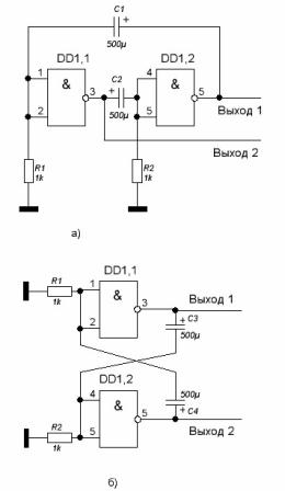
The multivibrator circuit is shown in Figure 1a. This circuit in appearance is very similar to the classic multivibrator circuit with transistors. Only here as active elements are applied logic elements microchips included by inverters. For this, the input pins of the microcircuit are connected together. Capacitors C1 and C2 form two positive feedback circuits. One circuit is the input of the element DD1.1 - capacitor C1 - the output of the element DD1.2. The other from the input of the element DD1.2 through the capacitor C2 to the output of the element DD1.1.
Thanks to these connections, the circuit is self-excited, which leads to the generation of pulses. The pulse repetition period depends on the ratings of the capacitors in the feedback circuits, as well as the resistance of the resistors R1 and R2.
In Fig. 1b, the same circuit is drawn in such a way that it is even more similar to the classic multivibrator version with transistors.
Fig. 1 Self-oscillating multivibrator
Electrical impulses and their characteristics
Until now, when we got acquainted with the microcircuit, we were dealing with direct current, because the input signals during the experiments were supplied manually using a wire jumper. As a result, a constant voltage of low or high level was obtained at the output of the circuit. Such a signal was random in nature.
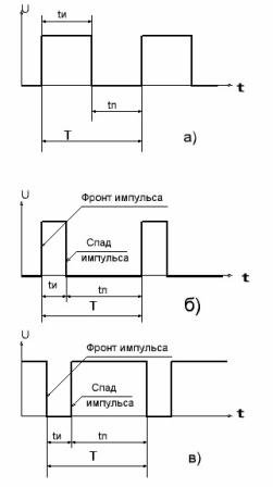
In the multivibrator circuit we have assembled, the output voltage will be pulsed, that is, changing with a certain frequency stepwise from a low level to a high one and vice versa. Such a signal in radio engineering is called a pulse sequence or simply a sequence of pulses. Figure 2 shows some varieties of electrical pulses and their parameters.
The sections of the pulse sequence in which the voltage takes a high level are called high-level pulses, and the low-level voltage is the pause between high-level pulses. Although in fact, everything is relative: we can assume that the pulses are low, which will include, for example, any actuator. Then a pause between pulses will be considered just a high level.
Figure 2. Pulse sequences.
One of the special cases of the pulse shape is the meander. In this case, the pulse duration is equal to the pause duration. To assess the ratio of the pulse duration, use a parameter called duty cycle. Duty rate shows how many times the pulse repetition period is longer than the pulse duration.
In Figure 2, the pulse repetition period is indicated, as elsewhere, by the letter T, and the pulse duration and pause time are ti and tp, respectively. In the form of a mathematical formula, the duty cycle will be expressed as follows: S = T / ti.
Due to this ratio, the duty cycle of the “meander” pulses is equal to two. The term meander in this case is borrowed from construction and architecture: this is one of the methods of bricklaying, the brickwork pattern just resembles the indicated sequence of pulses. The meander pulse sequence is shown in Figure 2a.
The reciprocal of the duty cycle is called the fill factor and is indicated by the letter D from the English Duty cycle. According to the above, D = 1 / S.
Knowing the pulse repetition period, it is possible to determine the repetition rate, which is calculated by the formula F = 1 / T.
The beginning of the impulse is called the front, and the end, respectively, the decline. Figure 2b shows a positive impulse with a duty cycle of 4. Its front starts from a low level and goes to a high one. Such a front is called positive or ascending. Accordingly, the decline of this impulse, as can be seen in the picture, will be negative, falling.
For a low-level impulse, the front will be falling, and the recession will increase. This situation is shown in Figure 2c.
After such a little theoretical preparation, you can begin to experiment. In order to assemble the multivibrator shown in Figure 1, it is enough to solder two capacitors and two resistors to the microcircuit already installed on the breadboard. To study the output signals, you can use just a voltmeter, preferably a pointer, rather than a digital one. This was already mentioned in the previous part of the article.
Of course, before you turn on the assembled circuit, you need to check if there are any short circuits and the correct assembly in accordance with the circuit. With the ratings of capacitors and resistors indicated on the diagram, the voltage at the output of the multivibrator will change from low to high no more than thirty times per minute. Thus, a voltmeter needle connected, for example, to the output of the first element, will oscillate from zero to almost five volts.
The same can be seen if you connect a voltmeter to another output: the amplitude and frequency of the arrow deviations will be the same as in the first case. It is not in vain that such a multivibrator is often called symmetrical.
If now you are not too lazy and connect another capacitor of the same capacity in parallel with the capacitors, then you can see that the arrow began to oscillate two times slower. The oscillation frequency decreased by half.
If now, instead of capacitors, as indicated in the diagram, solder capacitors of lower capacity, for example, 100 microfarads, then you can notice just an increase in frequency. The arrow of the device will fluctuate much faster, but still its movements are still quite noticeable.
And what happens if you change the capacity of only one capacitor? For example, leave one of the capacitors with a capacity of 500 microfarads, and replace the other with 100 microfarads. The increase in frequency will be noticeable, and, in addition, the arrow of the device will show that the time ratio of pulses and pauses has changed. Although in this case, according to the scheme, the multivibrator still remained symmetrical.
Now let's try to reduce the capacitance of the capacitors, for example 1 ... 5 microfarads. In this case, the multivibrator will generate an audio frequency of the order of 500 ... 1000 Hz. The arrow of the device will not be able to respond to such a frequency. It will simply be somewhere in the middle of the scale, showing the average signal level.
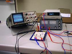
It is simply not clear here whether the pulses of a sufficiently high frequency actually go, or the “gray” level at the output of the microcircuit. To distinguish such a signal, an oscilloscope is required, which not everyone has. Therefore, in order to verify the operation of the circuit, it is possible to connect the head phones through a 0.1 μF capacitor and hear this signal.
You can try to replace any of the resistors with a variable of approximately the same value. Then, during its rotation, the frequency will vary within certain limits, which makes it possible to fine tune it. In some cases, this is necessary.
However, contrary to what has been said, it happens that the multivibrator is unstable or does not start at all. The reason for this phenomenon lies in the fact that the emitter input of TTL microcircuits is very critical to the values of the resistors installed in its circuit. This feature of the emitter input is due to the following reasons.
The input resistor is part of one of the arms of the multivibrator.Due to the emitter current, a voltage is created on this resistor that closes the transistor. If the resistance of this resistor is made within 2 ... 2.5 Kom, the voltage drop across it will be so large that the transistor simply stops responding to the input signal.
If, on the contrary, we take the resistance of this resistor within 500 ... 700 Ohms, the transistor will be open all the time and will not be controlled by input signals. Therefore, these resistors should be selected based on these considerations in the range of 800 ... 2200 Ohms. This is the only way to achieve the stable operation of the multivibrator assembled according to this scheme.
Nevertheless, such a multivibrator is affected by factors such as temperature, instability of the power supply, and even variations in the parameters of microcircuits. Microchips from different manufacturers often differ quite significantly. This applies not only to the 155th series, but also to others. Therefore, a multivibrator assembled according to such a scheme is practically rarely used.
Three-element multivibrator
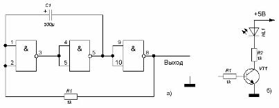
A more stable multivibrator circuit is shown in Figure 3a. It consists of three logic elements, included, as in the previous one, by inverters. As can be seen from the diagram, in the emitter circuits of the logic elements just mentioned resistors are not. The oscillation frequency is specified by only one RC chain.
Figure 3. Multivibrator on three logical elements.
The operation of this version of the multivibrator can also be observed using a pointer device, but for clarity, you can assemble an indicator cascade on the LED on the same board. To do this, you need one KT315 transistor, two resistors and one LED. The indicator diagram is shown in Figure 3b. It can also be soldered on a breadboard together with a multivibrator.
After turning on the power, the multivibrator will start to oscillate, as evidenced by the flash of the LED. With the values of the timing chain indicated on the diagram, the oscillation frequency is about 1 Hz. To verify this, it is enough to calculate the number of oscillations in 1 minute: there should be about sixty, which corresponds to 1 oscillation per second. By definition, this is precisely 1Hz.
There are two ways to change the frequency of such a multivibrator. First, connect another capacitor of the same capacity parallel to the capacitor. LED flashes became about half as rare, which indicates a decrease in frequency by half.
Another way to change the frequency is to change the resistance of the resistor. The easiest way is to install a variable resistor with a nominal value of 1.5 ... 1.8 Com in its place. When this resistor rotates, the oscillation frequency will vary within 0.5 ... 20 Hz. The maximum frequency is obtained in the position of the variable resistor when the conclusions of the microcircuit 1 and 8 are closed.
If you change the capacitor, for example, with a capacity of 1 microfarad, then using the same variable resistor, you can adjust the frequency within 300 ... 10 000 Hz. These are already the frequencies of the sound range, therefore the indicator glows continuously, it is impossible to say if there are pulses or not. Therefore, as in the previous case, you should use the head phones connected to the output through the 0.1 μF capacitor. It is better if the head phones are high resistance.
To consider the principle of operation of a multivibrator with three elements, let us return to its scheme. After the power is turned on, the logic elements will take some state not at the same time, which one can only be assumed. Assume that DD1.2 is the first to be in a high-level state at the output. From its output through an uncharged capacitor C1, a high level voltage is transmitted to the input of the element DD1.1, which will be set to zero. At the input of the DD1.3 element is a high level, so it is also set to zero.
But this state of the device is unstable: capacitor C1 is gradually charged through the output of the element DD1.3 and resistor R1, which leads to a gradual decrease in the voltage at the input DD1.1. When the voltage at the input DD1.1 approaches the threshold, it will switch to unity, and accordingly, the element DD1.2 to zero.
In this state, the capacitor C1 through the resistor R1 and the output of the element DD1.2 (at this time, its output is low) starts to recharge from the output of the element DD1.3. As soon as the capacitor is charging, the voltage at the input of the element DD1.1 will exceed the threshold level, all elements will switch to opposite states. Thus, at the output 8 of the element DD1.3, which is the output of the multivibrator, electrical pulses are formed. Also, pulses can be removed from pin 6 of DD1.2.
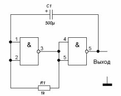
After we figured out how to obtain pulses in a three-element multivibrator, we can try to make a two-element, the circuit, which is shown in Figure 4.
Figure 4. Multivibrator on two logic elements.
To do this, the output of the resistor R1, right on the circuit, is enough to unsolder from pin 8 and solder to pin 1 of element DD1.1. the output of the device will be the output 6 of the element DD1.2. the DD1.3 element is no longer needed and can be disabled, for example, for use in other circuits.
The principle of operation of such a pulse generator differs little from what has just been considered. Suppose that the output of the element DD1.1 is high, then the element DD1.2 is in the zero state, which allows the capacitor C1 to be charged through the resistor and the output of the element DD1.2. As the capacitor charges, the voltage at the input of the element DD1.1 reaches the threshold, both elements switch to the opposite state. This will allow the capacitor to recharge through the output circuit of the second element, the resistor and the input circuit of the first element. When the voltage at the input of the first element is reduced to a threshold, both elements will go into the opposite state.
As mentioned above, some instances of microcircuits in the generator circuits are unstable, which may depend not only on a specific instance, but even on the manufacturer of the microcircuit. Therefore, if the generator does not start, it is possible to connect a resistor with a resistance of 1.2 ... 2.0 Com between the input of the first element and the "ground". It creates an input voltage close to threshold, which facilitates the start-up and the actual operation of the generator.
Such variants of generators in digital technology are used very often. In the following parts of the article, relatively simple devices assembled on the basis of the considered generators will be considered. But first, one more option of a multivibrator should be considered - a single vibrator, or a monovibrator in another way. With the story about him, we begin the next part of the article.
Boris Aladyshkin
Continuation of the article: Logic chips. Part 5
See also at bgv.electricianexp.com
:

