Categories: Practical Electronics, Novice electricians
Number of views: 87343
Comments on the article: 2
How to detect closed loops
 If physics was well taught at your school, then you probably will remember the experience that clearly explained the phenomenon of electromagnetic induction.
Outwardly, it looked something like this: the teacher came to the classroom, the attendants brought in some appliances and placed them on the table. After explaining the theoretical material, a demonstration of experiments began, which clearly illustrates the story.
Electromagnetic induction
To demonstrate the phenomenon of electromagnetic induction required inductor very large, powerful direct magnet, connecting wires and a device called a galvanometer.
The appearance of the galvanometer was a flat box a little larger than a standard A4 sheet, and behind the front wall, which was closed by glass, a scale with a zero in the middle was placed. Behind the same glass one could see a thick black arrow. All this was quite distinguishable even from the most recent desks.
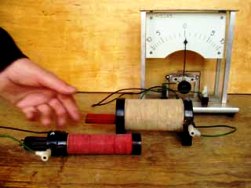
The galvanometer leads were connected to the coil using wires, after which the magnet simply moved up and down inside the coil by hand. The galvanometer needle moved from side to side to the beat of the magnet, which indicated that a current was flowing through the coil. True, after graduation, a friend of the physics teacher told me that on the back wall of the galvanometer there was a countersunk handle, which was used to manually move the shooter if the experiment failed.
 Now such experiments seem simple and almost not worthy of attention. But electromagnetic induction is now used in many electrical machines and devices. In 1831, Michael Faraday was engaged in its study.
At that time there were still not enough sensitive and accurate instruments, so it took many years to guess that the magnet should MOVE inside the coil. Magnets of various shapes and strengths were tried, the winding data of the coils also changed, the magnet was applied to the coil in different ways, but only the alternating magnetic flux achieved by the movement of the magnet led to positive results.
Faraday’s studies have proved that the electromotive force arising in a closed circuit (coil and galvanometer in our experience) depends on the rate of change of the magnetic flux, limited by the internal diameter of the coil. In this case, it is absolutely indifferent to how the change in the magnetic flux occurs: either due to a change in the magnetic field, or due to the movement of the coil in a constant magnetic field.
Self-induction, EMF of self-induction
The most interesting thing is that the coil is in its own magnetic field created by the current flowing through it. If the current in the circuit under consideration (coil and external circuits) changes for some reason, then the magnetic flux causing EMF will also change.
 This EMF is called the self-induction EMF. A remarkable Russian scientist E.Kh. studied this phenomenon. Lenz. In 1833, he discovered the law of interaction of magnetic fields in a coil, leading to self-induction. This law is now known as the law of Lenz. (Not to be confused with Joule-Lenz law)!
Lenz’s law says that the direction of the induction current arising in a conducting closed circuit is such that it creates a magnetic field that counteracts the change in the magnetic flux that caused the appearance of the induction current.
In this case, the coil is in its own magnetic flux, which is directly proportional to the current strength: Ф = L * I.
In this formula there is a proportionality coefficient L, also called inductance or self-inductance coefficient of the coil. In the SI system, the unit of inductance is called henry (GN).If, with a direct current of 1A, the coil creates its own magnetic flux of 1VB, then such a coil has an inductance of 1H.
Like a charged capacitor having a supply of electrical energy, the coil through which current flows has a supply of magnetic energy. Due to the phenomenon of self-induction, if the coil is connected to a circuit with an EMF source, when the circuit is closed, the current is set with a delay.
In the same way, it does not immediately stop when disconnected. In this case, the self-induction EMF acts on the coil terminals, the value of which is significantly (tenfold) higher than the EMF of the power source. For example, a similar phenomenon is used in ignition coils of cars, in horizontal scans of televisions, as well as in the standard scheme for switching on fluorescent lamps. These are all useful manifestations of EMF self-induction.
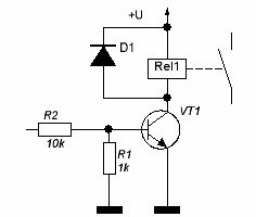
In some cases, the self-induction EMF is harmful: if the transistor switch is loaded with a coil of a relay coil or an electromagnet, then a protective diode is installed parallel to the winding to protect against EMF of the self-induction by the polarity of the reverse EMF of the power source. This inclusion is shown in Figure 1.

Figure 1. Protection of the transistor switch against EMF self-induction.
How to detect closed loops
Often doubts arise, but are there short circuits in the transformer or motor windings? For such checks, various devices are used, for example, RLC - bridges or home-made devices - probes. However, it is possible to check for short circuits using a simple neon lamp. Any lamp can fit - even from a faulty Chinese-made electric kettle.
To take a measurement, a lamp without a limiting resistor must be connected to the studied winding. The winding should have the greatest inductance; if it is a mains transformer, then connect the lamp to the mains winding. After that, a current of several milliamps should be passed through the winding. For this purpose, you can use a power source with a series-connected resistor, as shown in Figure 2.
You can use batteries as a power source. If at the moment of opening the supply circuit there is a flash of a lamp, then the coil is serviceable, there are no short-circuited turns. (To make the sequence of operations more clear, the switch is shown in Figure 2).
Such measurements can be carried out using a pointer avometer as a battery, such as a TL-4 in the resistance measurement mode * 1 Ohm. In this mode, the specified device gives a current of about one and a half milliamps, which is quite enough for the measurements described. Digital multimeter cannot be used for these purposes - its current is not enough to create the necessary magnetic field strength.
Similar measurements can be carried out exactly as well, if the neon lamp is replaced with your own fingers: to increase the resolution of the "measuring device", your fingers should be slightly slit. With a working coil, you will feel a fairly strong electric shock, of course not fatal, but also not very pleasant.

Figure 2. Detection of short-circuited turns using a neon lamp.
See also at bgv.electricianexp.com
:
