Categories: Practical Electronics, Novice electricians
Number of views: 68873
Comments on the article: 1
Logic chips. Part 1.
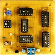 Introductory article about logic chips. Describes number systems and the representation of a binary number using electrical signals.
The modern digital integrated circuit is a miniature electronic unit, the housing of which contains active and passive elements connected in a certain pattern. These are transistors, diodes, resistors and capacitors.
The number of elements in modern microcircuits can reach several hundred thousand and even millions of elements. Just remember microprocessors, microcontrollers, memory chips.
To simply list all modern microcircuits, you will need not one article, but a whole rather thick book. In this article, we will consider microcircuits of small and medium degree of integration, mainly simple logic elements.
About twenty years ago Integrated Circuits (LSI)As a rule, they performed the function embedded in them during the manufacturing process. In one microcircuit a micro calculator, a clock or a node of an electronic computer (computer) could be hidden.
Currently widespread all kinds of microcontrollers: even such a simple device as Chinese-made Christmas garland there is nothing but a programmed microcontroller.
 Electronic clocks, household timers, various talking and singing toys are also obtained by programming the corresponding microcontroller. Or, as everyone is hearing now, a flashing.
In other words not programmed controller This is the disc from which the device with the properties necessary for the developer will be obtained. And, despite such universality, the input and output signals of the microcontroller are the same as the digital microcircuits of small and medium degree of integration. Therefore, without knowledge of these already obsolete and forgetful elements, there is simply no way to go.
At the heart of the work digital circuits lies a binary number system. It also underlies the operation of modern personal computers and all computing and communication systems.
 In everyday life, we use the decimal number system containing ten digits 0 ... 9. Such a system came about because each person has ten fingers on his hands. Some peoples of the North counted up to twenty, and the number twenty was called "the whole man."
Ten is no longer a digit, but a number consisting of one ten and zero units: 10 = 1 * 10 + 0 * 1. In exactly the same way, the number 640 will contain six hundred + four tens + zero units, or in the form of numbers 640 = 6 * 100 + 4 * 10 + 0 * 1.
Such a system is called a decimal positional, i.e. the weight of the discharge depends on its position in the number. It is easy to notice that these will be units, tens, hundreds, thousands, tens of thousands, hundreds of thousands and so on.
In a binary system, a number is obtained in exactly the same way, but not ten, but two and its degree are used as the basis. That is, not 1, 10, 100, 1000, 10000, and so on, but 1, 2, 4, 8, 16, 32, 64, 128. Each subsequent number is obtained by multiplying the previous one by the base of the system (in this case, by 2), those. raising the previous to the next degree. For the decimal system, each previous number is multiplied by ten, since the base of the number system is ten.
Using an eight-bit binary number, (byte is called in computer technology) it is possible to represent decimal numbers in the range 0 ... 255, or in binary form 0000 0000 ... 1111 1111 (b).
The number 640 mentioned above will correspond to the entry 640 = 10 1000 0000 (b) or, as in the previous example
640=1*512+0*256+1*128+0*64+0*32+0*16+0*8+0*4+0*2+0*1.
(b) at the end of the record indicates that the number is binary.The easiest way to verify the correctness of this entry is with the Windows calculator. This form of encoding information turned out to be very convenient for computers, because it’s as easy to distinguish zero from one as a closed contact from an open contact or a burning lamp from an extinct one.
 If binary information is transmitted using electrical signals, then only two voltage levels are required. As a rule, it is more positive (high), and less positive or even negative (zero).
Most often, a high level voltage is considered to be a logical unit, and a low level voltage is considered a logical zero. Then they say that we are dealing with positive logic.
In addition, there is also negative logic: a high level voltage is a logical 0, and a low level is a logical unit. In this article we will consider only positive logic.
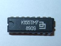 One of the most common and popular at the time among radio amateurs was microcircuits of the K155 series. For them, the logic zero voltage is at the level of 0 ... 0.4V, and the logical unit is 2.4 ... 5.0V. This is despite the fact that the rated supply voltage for this series is 5V with a tolerance of + - ten percent.
For other series of microcircuits having a different supply voltage, these numbers are, of course, different, but within the same series, unchanged. Roughly we can say that the voltage of a logical unit in most series of microcircuits ranges from half the supply voltage to the full supply voltage.
For example, for K561 series microcircuits with a supply voltage of + 15V, the logical unit voltage will be in the range + 7.5 ... 15V. The K561 series is operable with a supply voltage within 3 ... 15V. In this case, the voltage of the logical unit will be within the limits indicated above.
We will consider the description of logical circuits using the K155 series as the most common and do not require special precautions during operation.
This series of chips is considered functionally complete and contains about 100 items. This means that with this series you can implement any even the most complex logical function.
In the next article we will get acquainted with the operation and device of digital microcircuits. We will begin this acquaintance with logic elements that implement the simplest functions. Boolean algebra (algebra of logic).
Boris Aladyshkin
Continuation of the article: Logic chips. Part 2.
EBook -Beginner's Guide to AVR Microcontrollers
See also at bgv.electricianexp.com
:
